By:
Category:
Comments Off

Arduino based DDS-60 controller for QRSS

I stumbled across an interesting email from "the Knight's" mailing list from Ross KB1KGA.

The Knights is an email list that is focused on QRSS building and operation. It tends have a lot of participation from Europe and Australia with some momentum building in the US and Canada.   The reflector is located at: http://mail.cnts.be/mailman/listinfo/knightsqrss_cnts.be  QRSS is a good topic to investigate if you are interested in QRP and especially if you are a "builder."

Here is an excerpt of the email:


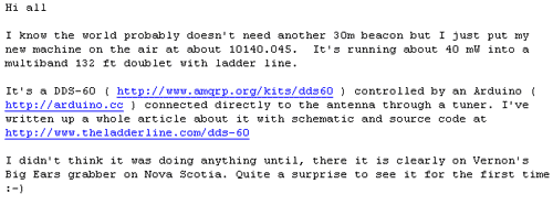
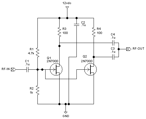
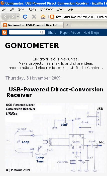
I bet that he has pictures and a schematic at that link....
http://www.theladderline.com/node/10


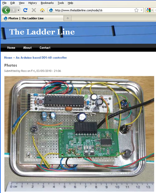
Click around on the links. He includes a schematic and some details on the project.

Notes:
The Arduino community has a lot of traction at the moment.  I am really impressed with amount of people talking about the Adunio project board and Atmel in general. I happen to be investigating the Microchip based PIC platform at the moment but the Atmel folks are really making me think that I should revisit my platform choice. Most the folks that I know locally and through work happen to be focused primarily on the PIC so has influenced me since I can lean on them for support.  :-)

73 de NG0R


By:
Category:
Comments Off

XV432 Night One

I worked on the main RF board tonight off and on 10-15 minutes at a pop.

The board is slightly different than the ones for the XV144 & XV222. While very similar there are subtle differences and you can probably pick some of them out from the picture.  :-)

So far the construction is going ok. There were a couple of parts that I had hard time finding that appear to be in the finishing bag instead of the main bag which is slightly different that the parts bags for the XV432. Most people would probably not notice the inconstancy in the part bags because they are not building two transverters back to back.

I should be able to find an hour or two on Sunday to spend on this project. I am getting down to the inductors, filters, and some other small parts that were hidden in the "432 finishing" parts back like a 2 watt resistor. I think that kit will should largely be assembled tomorrow (Sunday.)

73 de NG0R

By:
Category:
Comments Off

XV432 Day One

The project has started....


The front panel pcb is done. It is a mix of the parts on the front and on the back. It is a pretty simple board with probably about 3 dozen components. Once the parts are sorted this takes about 45 minutes to stuff the parts, solder, and trim.

73 de NG0R

By:
Category:
Comments Off

XV144 Night Three

I finished the transverter Thursday night but did not post the notes to the blog. I have held the post for a couple of days while I was migrating the content from my old blog/server to the new blog/server.

I will try to post a follow-up picture later this weekend if time permits.

I will wait to test & adjust the XV144 until I am done with the XV432 kit. I figure that I might as well deal with the XV144, XV222, XV432 and K2 all at the same time as migrate these to an Elecraft centric approach to the shack integration.

I just popped the box open for the XV432 kit. I hope to make a dent on the construction this weekend.

73 de NG0R

By:
Category:
Comments Off

Updated Website

I am in the process of migrating my website, blog, email, and DNS to a different hosting provider. My previous provider (and a good friend) was migrating all of his hosting and clients from a Windows based IIS server to a Unix server.


I had already been pondering changing from Windows + IIS + DasBlog to Linux+WordPress. The timing + details of the upstream changes prompted me to make some other changes at the same time.

Process:
  • I tried using the BlogML export tool (which works very well) with some BlogML Wordpress plug-in's for the migration process. The export worked but the import with the plug-in did not work with Wordpress 2.9.2. 
  • I ended up just changing my RSS settings on DasBlog to show 500 enteries in the feed and then saved the feed as a XML file. I then used the built-in RSS import tool to import the old posts.
  • I then moved the images and other related content via FTP.
  • I previewed the posts and content using a ww2.hoaglun.com address. Once everything looked ok I migrated the DNS for www.hoaglun.com over to the new host this morning.

Follow-up items:

  • I need to migrate my DNS over to GoDaddy
  • I need to setup my mail at my new provider
  • I need to migrate my mailboxes via IMAM
  • Write a new front page to do image rotation like the old site. (It was written in ASP so I will probably need to write the new one in PHP or Ruby on Rails
  • I need to determine how I want to how the family photos in some sort of gallery.
  • I will probably build a new blog for a "photo of the day" or "photo of the week" kind of activity
This is the first test post on the new site. So far I am pretty happy with how the migration is going.

PS... the post worked, the edit worked, and the picture got posted. It looks like I am in business on the new server.


By:
Category:
Comments Off

XV144 Night Two

The main RF board is coming along nicely on the Elecraft XV144.


N2BEN is pleased with our progress for the day. We are getting to the hardware pieces
like BNCs, DB9, and the final RF stage. The parts box is starting to look a bit empty
after today's progress.

I did run into one issue. They did not ship any .01uF capacitors. I went through the
parts bags a few times and the shipping box.  Ok,  no big deal as I probably
have a bunch of them in my parts boxes stocked up for other homebrew projects. Arghhhh....
they are a different size leg width than the 100 that I have have on hand from a recent
parts order. I then hunted around a bit more and found a bunch of ceramic disk capacitors
of the proper value with flexible legs in the bottom of my capacitor parts box.

I will wait to call Elecraft about the issue until I finish the project in case they
show up stuck in side of another bag as I finish this unit up. Once this unit is done
we have a XV432 kit to build so it will be interesting to see if that parts bag looks
ok.

PS.... I found the small envelope of capacitors. It was stuck to the envelope for the thermal pads. Once I got to that step on Night three I found them... go figure.

By:
Category:
Comments Off

N2BEN + transverter + bench time


Ben (N2BEN... age 9) has been asking me for a few days if we could build a project
or kit again. (A sign that he either has "the knack" or cabin fever.) So tonight I
pushed my home brew projects a side pulled out my box of Elecraft
transverter kits
. I have a XV144 and XV432 that are awaiting some bench time to
get built. (I have a completed XV222 that I have been using for about 2 years.)


So tonight we started the XV144 kit. We sorted the components into project boxes for
temporary storage. We then assembled the front board. There are probably about 3 dozen
components. I read the directions and handed the parts to Ben and then he put the
parts onto the circuit board. We shared the soldering duties... he ran the iron and
I ran the solder.


We probably spend about 70 minutes tonight on the project.


It will be fun to plug these into the K2 once the project is done.


73 de NG0R


By:
Category:
Comments Off

Playing with PCBs and 2N7000 amps

I am planning on making some printed circuit boards this weekend. Since I need to get out the chemicals & related supplies I might as well make several boards.  So in addition to the board for the parallel NPN transistors I thought that I would make up some 2N7000 FET experiments as well.


The circuit below is a dual FET design. The FETs are in parallel running in class
A. The Gate is biased for approximately 2 volts of DC drive with virtually no current
with assuming a bench power supply of 12-13.5 volts. (R3 and R4 are high values
for current limiting aka to avoid self destruction.)
The 2N7000 is rated for 200mA
of safe current. (200mA would suggest a drain resistor of approximately 68ohms.) I
don't really want to waste that much current but I want to see what this will draw.
I would prefer that it consume current less than my NPN experiments which is about
25mA per device with 15 to 17dB of gain per device. (I assume that I will be changing
the drain resistors once I know more about this FET.)


The image below shows what it looks like after spending a little bit of time bonding
with FreePCB.  (The blue circle in the bottom left is a small hole to hold/retrieve
the board in the etchant bath.)


The image below shows what the copper will look like (in black.)   The white
areas will be removed by the etchant. The board looks big on the web but it is actually
only about 1.5 x 1.5 inches total. (If I removed the text and extra space it could
easily be condensed down to less than 1 x 1 inch.)


I don't know that I would would ever really use a design like this in the real world
but I want to get a feel for how it performs. I have NOT used FETs in any of my designs
or experiments yet so this is a good starting point.


Bipolar Junction Transistors are current devices. Field Effect Transistors are voltage
devices. It is interesting working with each of them as they have different design
considerations.


Some additional notes (before people start sending me emails):


  • The input impedance of this circuit is pretty high. It is not clear what high impedance
    is other than to say it could be way north of 1K. In this initial test I am not making
    any attempt to match the input. (That is why it is test.)


  • If I was going to try to match the input to something like my signal generator I would
    probably use a 1:4 or 1:5 turns ratio to take the 50 ohm source and transform it to
    between 800 and 1250 ohms.


  • The output of this should be approximately what the drain resistor value is. In this
    case it should see two 100 ohm resistors in parallel or 50 ohms. (I might be changing
    these resistors once I do some testing so it is a bit early to be too worried about
    matching the circuit. I would also need to now what the next circuit stage is that
    we need to integrate with.)
    It would be easy enough to wind a transformer on a
    T50-43 core to step-up/step-down as needed.


  • FETs are voltage sensitive.   Looking at the data sheet it appears that 60 volts
    is the max that the 2N7000 can handle. In a design for a "real" circuit it might be
    worth considering adding a zener diode to the drain to shunt off the excess voltage
    should it appear. (An example is running this circuit without having a load attached...
    it could spike the voltage on the drain to a fatal level. I have a limited number
    of 33 volt zeners on hand but that would potential for a design like this. For this
    test I am not going to worry about it. If I decide to use FETs in a "real" project
    I would probably include them.)


73 de NG0R


By:
Category:
Comments Off

USB-Powered Direct-Conversion Receiver

G1INF has an interesting example to demonstrate how simple a DC receiver can be.


http://g1inf.blogspot.com/2009/11/usb-powered-direct-conversion-receiver.html


I happen to have some SA602 on hand from a Mouser order that I placed last week. I
figured that it might be nice to have some on hand for some future projects. (I have
not worked on building any receivers yet as I am focused on simple oscillator driven
transmitters and how to build small signal gain stages at the moment.)


An interesting note in this blog post is that input impedance of the SA602 is 1500
ohms. I did not realize that but I have never really looked at the data sheet for
the SA602 in detail.


Here is a link to the datasheet:

http://www.nxp.com/documents/data_sheet/SA602A.pdf


Here are some of more interesting excerpts:


Good geeky stuff from the the blog world.


73 de NG0R