By:
Category:
Comments Off

WSPR results?

What does my shack do when I am stuck working and can't play?  --Sit and listen to WSPR beacons
and post them to the internet.


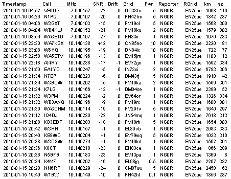
The table below shows all the unique stations that I have heard over the past 3-4
days that are doing better than 1000 miles per Watt sending WSPR.  Most of these
have been heard using my Elecraft K2, 160m antenna, WSPR running on Linux. (The
160m antenna is a 56 foot tall shunt loaded tower with about a dozen radials.)


Date and Time

Sending Call

Freq

Pwr in Watts

Miles

Miles per Watt

01/17/10 04:56 PM

W3PRB

10.1402410

0.001

1572

1572000.00

01/15/10 07:40 PM

W1BW

10.1401490

0.100

1856

18560.00

01/17/10 04:50 PM

DL1EL

10.1401380

0.500

7047

14094.00

01/19/10 02:12 AM

EA1RJ

3.5941420

0.500

6850

13700.00

01/17/10 09:36 PM

WJ2V

10.1401430

0.200

1747

8735.00

01/16/10 01:00 PM

N0GSZ

7.0401070

0.200

1682

8410.00

01/15/10 08:36 PM

IQ4DJ

10.1402330

1.000

7618

7618.00

01/18/10 03:48 PM

PA2PF

10.1402230

1.000

6695

6695.00

01/17/10 02:50 AM

G7DOM

3.5940950

1.000

6240

6240.00

01/15/10 07:38 PM

K4MF

10.1402070

0.500

2207

4414.00

01/17/10 05:36 PM

DG1SGH

10.1402140

2.000

7212

3606.00

01/19/10 02:18 AM

N1DYL

3.5940930

0.500

1799

3598.00

01/16/10 10:54 PM

EA8/LA3JJ

7.0401710

2.000

7071

3535.50

01/15/10 09:38 PM

EA1YO

10.1402590

2.000

6783

3391.50

01/16/10 07:48 PM

WA4DAW

7.0401050

0.500

1548

3096.00

01/19/10 05:08 PM

GI6ISW

14.0971540

2.000

5964

2982.00

01/15/10 07:50 PM

K7LG

10.1401730

1.000

2389

2389.00

01/16/10 05:08 PM

K0AWU

7.0400270

0.100

224

2240.00

01/17/10 01:02 AM

W7RDP

7.0400680

1.000

2133

2133.00

01/15/10 07:38 PM

W3HH

10.1401620

1.000

2083

2083.00

01/18/10 08:18 PM

NJ6D

10.1401930

1.000

2018

2018.00

01/17/10 02:50 AM

N7KJW

3.5941150

1.000

1963

1963.00

01/17/10 05:22 PM

JQ2WDO

10.1402200

5.000

9604

1920.80

01/17/10 02:08 PM

K0FT

3.5940770

0.500

887

1774.00

01/17/10 09:44 PM

W3FIS

10.1401140

1.000

1749

1749.00

01/17/10 02:08 PM

VK6POP

3.5941010

10.000

17008

1700.80

01/16/10 03:54 AM

WA3ETD

7.0401070

1.000

1670

1670.00

01/16/10 05:20 PM

VA2DC

7.0400980

1.000

1625

1625.00

01/15/10 08:24 PM

WB3ANQ

10.1401990

1.000

1608

1608.00

01/18/10 05:16 PM

K8KCX

10.1402460

0.500

800

1600.00

01/15/10 10:18 PM

AI4RY

10.1402380

1.000

1592

1592.00

01/15/10 07:38 PM

W3CSW

10.1402780

1.000

1562

1562.00

01/19/10 05:00 PM

OE3BWW

14.0971870

5.000

7622

1524.40

01/16/10 09:22 PM

DF6MK

7.0400380

5.000

7427

1485.40

01/18/10 03:28 PM

DC6MY

10.1402330

5.000

7310

1462.00

01/17/10 05:36 PM

HB9BYC

10.1401580

5.000

7277

1455.40

01/19/10 05:06 PM

DL7VEA

14.0971420

5.000

7168

1433.60

01/17/10 04:28 PM

DL1BNO

10.1401950

5.000

7111

1422.20

01/17/10 05:14 PM

DF5FF

10.1402480

5.000

7093

1418.60

01/18/10 04:12 PM

DL5ZAA

10.1401620

5.000

7085

1417.00

01/17/10 03:12 AM

DH8SA

3.5941150

5.000

6998

1399.60

01/16/10 11:42 PM

EA4AS

7.0400880

5.000

6967

1393.40

01/17/10 05:24 PM

DF2JP

10.1401630

5.000

6900

1380.00

01/15/10 07:44 PM

N5BFB

10.1401860

1.000

1369

1369.00

01/17/10 02:56 AM

PA1NL

3.5940990

5.000

6782

1356.40

01/18/10 03:20 PM

ON7KO

10.1402110

5.000

6763

1352.60

01/19/10 02:16 AM

OH8GKP

3.5940880

5.000

6719

1343.80

01/15/10 07:38 PM

W3PM

10.1402330

1.000

1326

1326.00

01/16/10 11:34 PM

G8HXE

7.0401630

5.000

6253

1250.60

01/18/10 09:30 PM

WA7RED

10.1402570

1.000

1143

1143.00

01/15/10 10:58 PM

WA5ETV

10.1401960

1.000

1103

1103.00

01/19/10 02:10 AM

W0AEW

3.5940760

1.000

1044

1044.00


Okay, that was my lunch time distraction... time to go back to work.


73 de NG0R


By:
Category:
Comments Off

Directional Coupler (Version Two)

This project is the follow-up to the Pine
Board Directional Coupler
that I built & tested a couple of weeks ago. That
project was largely based upon information from Sprat and Elecraft. (Links to the
info is at the end of the post below.)


I plan to use this with my Spectrum Analyzer as I need a safe way to sample levels
low enough for the scope. (I am not a fan of using attenuation pads if "real power"
might be involved as they could open up and present high power to the test tools if
they fail. Most pads are only rated at 2w.)


Goals:


  • Build a directional coupler with a port that is -20db from the reference signal. I
    am primarily working at HF frequencies for my current design work but would like to
    have basic VHF or even moderate UHF coverage if possible.


  • The ability to run real power through the unit if needed. (100w)


  • It should be easy to build.


  • It should allow for reproducible test results across other replicas of the unit.


The wire lead lengths were minimized where possible. Most of the part could easily
be scrounged from a junk box if you are a well equipped hobbiest... or my case some
of the parts from the internet. (Digikey, eBay, and kitsandparts.com)


Schematic and parts:


2 - T50-43 toroid (kitsandparts.com)

3 - BNC connectors (eBay from China)

2 - 100 ohm 1w resistors (non inductive from Digikey)

1 - standoff (Digikey)

1 - Hammond 1590B case (Digikey)

Misc Wire (12 gauge and 20 gauge from the junk box)


If you follow the schematic as guide a to the physical wiring of this project you
should be fine. (Think of it as plumbing.)


I am going to leave the theory explanation to others because I do not completely
understand the exact science that is going  in that little box well enough to
be able to explain it to others. Check the links at the end of this post and I will
give you some good sites to visit for more information.


Measurement:


I went to N0FP's QTH to do the measurements.
We did a baseline calibration to normalize things like the cables, signal generator,
and the RF power meter. We used a Boonton
4220 RF power meter
for this round of data capture. I plotted everything manually
into OpenOffice on my laptop and then brought the data home where I could work with
it in more detail. (I have the data from 1mhz to 1100mhz)


The new coupler is at ~ -20db  from 1mhz to 120MHz.


--It is flat within .5db from 1mhz to 125mhz.


--It is within 2db +/- out to near 400mhz.


What does the data mean:


Looking at the graph shows that it is a good HF and VHF coupler but then loosens up
at UHF. I wanted to try to understand why it is moving around at UHF. The final project
has shorter wire lengths than the original Pine Board version but the trends were
similar. (I plotted {in yellow} a low power coupler from MiniCircuits as part of
the test. It was something that N0FP had on hand while we were testing so it was an
interesting comparison.)


After looking at the data I decided to plot the wire length to see if maybe we seeing
goofy response because of a 1/4 or 1/2 wavelength of wire. The table below plots the
number of turns, DB of coupling, wire length, frequency.


Sure enough it appears that the wire length is correlating to the data that I had
plotted from the couple of test runs. I think that it is possible to make this stable
at higher frequencies by moving from a -20db design to a -30db design. The challenge
is that the power levels at -30db might become low enough for small signal work that
the signal simply disappears in some cases.


Summary:


  • I have a nice directional coupler that is very accurate for HF and VHF testing. (It
    is usable at VHF with the reference table.)


  • I have not (yet) tested it with 100w in but I would have no concerns with it
    at that power level. (Most of my testing will not be higher than 5-10w.... probably
    even lower than that.)


  • It is a pretty simple project that can be assembled in less than two hours.


  • The accuracy is reproducible as long as excess wire lengths are kept under control.


  • The parts are all readily accessible.


Links:


GQRP/SPRAT article by David
Stockton - G4ZNQ


http://michaelgellis.tripod.com/direct.html


Calculator


http://www.elecraft.com/manual/CP1%20Manual%20Rev%20A.pdf


http://mjrainey.googlepages.com/qrppinlinedirectionalwattmeter


http://www.microwaves101.com/encyclopedia/directionalcouplers.cfm


http://www.e-meca.com/tech_papers/directional-coupler-specs.php


By:
Category:
Comments Off

WSPR - 30m

While I was working today and sitting on conference calls I decided to leave my radio and computer on to listen to 30m WSPR and post spots to the internet.


http://wsprnet.org/drupal/wsprnet/map


I heard two stations from Europe which I thought that was pretty neat.


I heard IQ4DJ when the beacon was running 50mW and 1w.  That is a pretty good
path for 50mW.


Today is the first time that I have played with WSPR. It looks pretty neat and is
going to be worth designing a radio for that portion of the hobby. It will probably
be a crystal driven rig since I have not yet moved up to DDS designs... yet. 
:-)


---

One update @ 11pm local.   Here is the list of unique stations that I heard
today with WSPR.


By:
Category:
Comments Off

DDS from Analog Devices

I am doing some initial research on readily available DDS chips. Analog devices has nice web page that allows you to download an Excel doc based upon your query for devices. (Click
on the table below to get to the exact page that has the Excel export options.)


http://www.analog.com


When time permits I need to look around at some other vendors to see what else is
available to the marketplace.


By:
Category:
Comments Off

PreScaler Ideas (PIC Freq Counter)

I am thinking about using a prescaler attached to a PIC to get a simple frequency counter. I would suspect that it would just become a "module" that I include in some other design projects later. Initially I need to get a working sample. Target range would be 1mhz through 400mhz.


This table shows what the math might look:


One component that I am looking at is a MC12080:


I have seen some other folks using the MC12080 as their prescaler. I would assume
that there are some other options if I hunt around a bit.


The image below is from the AA0ZZ PIC-EL
III manual as simple circuit for a simple frequency counter.


I need to layout a schematic and then put together a parts list and visit Digikey.
I think that these are all common parts that I can order from a single source. 
Getting the parts will be easy... the code to make this work in the PIC might be quite
a bit more complex.


By:
Category:
Comments Off

PIC-EL III - Frequency Counter

It just so happens that I own a really nice PIC-EL III. It is
a PIC programmer & development board that Craig
AA0ZZ
designed. I thought that I remembered that he might have a simple PIC based
frequency counter design in the manual.  A quick little search and presto.


------snip----------


http://cbjohn.com/aa0zz/PIC-EL-III/PIC-EL-III-Manual.pdf


page 11


2.2.8 Signal Conditioner A signal conditioner, shown in Figure 10
is provided to increase small amplitude signals to voltage levels which are detectable
by the PIC. The output amplitude of the DDS Daughtercard is too low to be fed directly
back into a PIC pin for the demonstration of frequency counting. To make this work,
the amplitude is increased by the signal onditioner circuitry. Notice that this conditioner
is not a linear amplifier in that it does not attempt to keep a distortion-free sine-wave
output. For purposes of frequency measurement, a square wave would be just as good
as a sine wave.


Figure 10– Signal Conditioner


Note that header HDR2 is used to select the source of the signal which goes into the
“conditioner”. In one position (jumper from HDR2 pins 1 to 2), the output of the DDS
Daughtercard is fed into the  “conditioner” while in another configuration (jumper
from HDR2 pins 3 to 4) a signal from an external source can be brought into the PIC-EL
board via the BNC connector (J7) and routed through the Note that header HDR2 is used
to select the source of the signal which goes into the onditioner”. In one position
(jumper from HDR2 pins 1 to 2), the output of the DDS Daughtercard is fed into the
conditioner” while in another configuration (jumper from HDR2 pins 3 to 4) a signal
from an external source can be brought into the PIC-EL board via the BNC connector
(J7) and routed through the “conditioner” before going to the PIC. (Another option
is to route the DDS output directly to the BNC, bypassing the “conditioner”, by installing
a jumper between HDR2 pins 2 and 3.) The sensitivity of the signal conditioner on
the PIC-EL III is about 100 mv P-P at 7 MHz.


------snip----------


I have not done much work with the board since I assembled it recently. (Lot of projects
on the bench these days.) This might be an excuse to pull out the board and see if
I can get it running as a simple freq counter. Maybe this can be scaled to work with
the RF power meter project that I am researching.


By:
Category:
Comments Off

PIC freq counter notes

I am capturing some notes for how to use a PIC MCU as a frequency counter. I would like to potentially include this in some other projects that I am looking at. There are some interesting ideas and the counter does not look too complex. I wonder if a person could prototype it to the point where it is a reproducible "component" that could be easily included in other designs.


http://www.piclist.com/techref/piclist/weedfreq.htm


http://www.qsl.net/dl4yhf/freq_counter/freq_counter.html


http://www.qsl.net/dl4yhf/qrp/index.html#miss_mosquita


http://www.qsl.net/dl4yhf/index.html#dl4yhf_winpic


http://www3.sympatico.ca/richard.blackman/PIC_LED_FREQUENCY_COUNTER.html


http://py2rlm.sites.uol.com.br/FREQLEDEGL.HTM


http://www.best-microcontroller-projects.com/support-files/pic-frequency-counter-lcd-tmr1.pdf


http://www.qsl.net/yo5ofh/pic/freq_counter/freq_counter.htm


http://www.hamradioindia.org/circuits/fcountlcd.php


http://www.embedds.com/the-marvelous-ik3oil-16f84-pic-frequency-counter/


http://ironbark.bendigo.latrobe.edu.au/~rice/newfm/newfm.html


With a prescaler - http://ironbark.bendigo.latrobe.edu.au/~rice/newfm/ghzfm.html


http://kl7r.ham-radio.ch/ik3oil/index.html


It seems like there is a lot of potential for reuse for a tool/module like this. I
will try to look into this more tonight after the kids go to bed. There is no end
to amount of reading that I can come up with.


By:
Category:
Comments Off

RF Power Meter Project

N0FP and I are investigating RF
power meter ideas. There are a lot of designs based upon the AD8307 A to D converter.
Many of the design variations originate with the W7ZOI design.
I decided to convert his design from the June 2001 QST article into a TinyCad schematic.


The image above is my first pass at the initial schematic capture. I might be missing
components or have typos in there... but this is the starting point. (Click on the
image and it will open a larger version with more detail.) The initial schematic
was not too hard. I had to create new parts for the AD8307 and the LM386 but that
only took a couple of minutes. I probably have about 60 minutes or so of time into
this schematic once I filter out all of the interruptions.


We are looking at prototyping this project and potentially adding some features to
make the design our own. I suspect the analog meter is not long for this project but
I will hold back on some of the new ideas until we get a bit further down the road
as there is quite a bit of research and testing to do before we get too crazy.


If you are interesting learning more about this project or participating please ping
me directly.


73 de NG0R


---


Some follow-up notes on 2010-01-10:

http://www.ka7exm.net/pic_power/index.htm


http://www.ka7exm.net/pic_power/ProjectNotes/x.pdf


Roger has a nice update to the original W7ZOI design that was published back in 2001.
I have other design and feature ideas so I don't think that I am going to order/build
Roger's design but will instead likely work through something on my own path.


73 de NG0R


By:
Category:
Comments Off

PCB Design Thoughts

I have been talking with N0FP directly on other folks via email about my time spent trying out some different EE cad tools. A couple of common questions seem to continue to come up....


  1. How do you move between LTSpice and a CAD program like TinyCad, Eagle, or KiCad?

    Being able to import/export with LTSpice is a big deal if you want to easily model
    your projects.


  2. Auto numbering of parts - This is a great feature if you can use and still go back
    and tweak the component numbers by region on the board or completely renumber if you
    add a part to the board, etc.


  3. Making a new part - I need to test how easy/complex it is to make a new raw part/component
    for the schematic & layout tool.


  4. Good auto router integration - So far TinyCad+FreePCB has had the output from the
    auto router. I still need to get this working with Eagle prior to buying Eagle...
    if I buy Eagle.


By:
Category:
Comments Off

Eagle - W7ZOI schematic example


The picture above is a quick schematic that I whipped up over lunch using the Freeware/eval
version of Eagle.  This took about 10-15 minutes to draw and it was my first
time using the tool. If I had a bit more time I would fill in the values of the components.
When time permits after work or over lunch I will try to see if I can finish this
and then move it to the PCB layout portion of the software.


I have to say that the "wires" were the easiest to lay down with Eagle. I think that
Eagle is a bit click and menu intensive initially compared to TinyCad. That might
be an initial feeling that changes once I learn the shortcuts and use the tool some
more.


My initial impression is that I like it at about the same level as TinyCad and more
testing is needed.


73 de NG0R

---------

Here are some additional follow-up notes later in the day (after work.)


  • I updated the schematic with values.


  • I ran into some problems with the part numbering because it auto numbers the parts.
    I could not find an easy to turn off that feature. That created an issue if a part
    number was already in use... I had to work around that goofy issue for 15 minutes.
    If my board was more complex this solution would have been unworkable.


  • I then ran the rule check (almost all schematic capture programs have this feature)
    and the seemingly easy wire routing turned out to have quite a few junction issues.
    (This was similar to the issue that I had with TinyCad.) So I clicked on each error
    and then added a junction to fix the problem.


  • I then exported a netlist and partslist. (Which did not seem to work properly with
    LTSpice... I will have to research this further.)


  • I then decided to layout a board. Hmmm... no auto parts placement. (Only one tool
    has really had that option.


  • Ok... the I will manually place the parts... wait I can't grab/move the toroid/transformer.
    I spent 10  minutes on this and final gave up.


  • Fine... lets run the auto router to put down some traces... oh wait... there is an
    error. This feature appears to be disabled in the Light Version even though the website
    says that it should work. Maybe there is an issue between the free/demo version and
    the Lite version.


So my follow up impression:


  • I REALLY like the look of the schematic. The layout was very fast and would
    get faster as a person gets to know the tool. The component library is HUGE.


  • I am really upset that the auto router does not work. I am really upset at the stupid
    part naming issue. I am disappointed with the board layout tool as I could not move
    the transformer.


I am so close to loving this tool and being willing to buy the Lite version for
$50... BUT... I could not complete a board with it and I can with TinyCad + FreePCB.


I will try to spend some more time later tonight or tomorrow evaluating this further...
it is time for dinner with the family.


73 de NG0R