By:
Category:
Comments Off

Pine Board Directional Coupler

I recently bought a spectrum analyzer and have been nervous about over driving the input to the scope. I also bought a step attenuator which will help control the levels but I still did not feel that I had this dialed in. I decided that I needed a directional coupler. Of course anyone could go buy one from MiniCircuits or eBay but what fun would that be. Most of the units on eBay were for microwave bands and up. Most of the units from MiniCircuits were rated for very low power... something like 2 watts in.


I wondered what it might take to build one... it is a geek/knack victim approach to
solving this challenge.


Some good reading on the topic:

http://michaelgellis.tripod.com/direct.html


http://www.elecraft.com/manual/CP1%20Manual%20Rev%20A.pdf


GQRP/SPRAT article by David
Stockton - G4ZNQ


Mechanically they look pretty simple... electrically I am not 100% certain how we
are figuring out forward power from reverse power. Is it the difference in phase on
each side of the toroid or some other evil EE magic?


I found a calculator
on the internet
that I could download and use to model coupling vs. the number
of turns. This calculator matches the data in the Sprat article and the info from
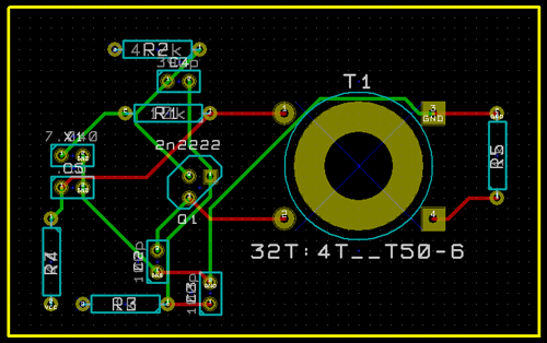
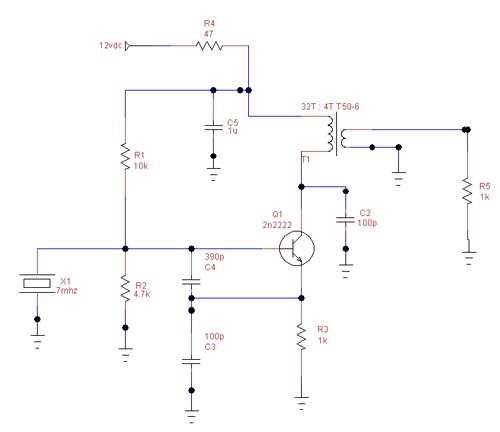
the Elecraft website fairly closely. The schematic below shows what I ended building.


Looking at the schematic we have two toroids, three BNC chassis mount connectors,
and two 100ohm 1w non-inductive resistors. (I found the resistors on the Digikey website...
I was looking for Carbon Comp and found these.) So that parts are not too magical.


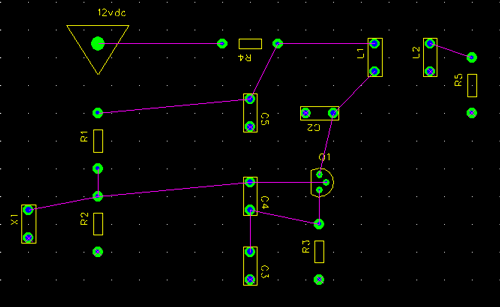
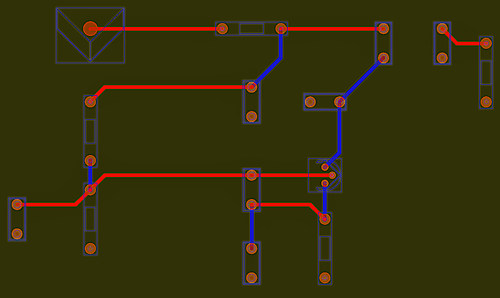
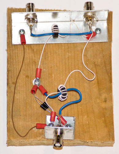
Looking at the pine board picture (below) you will notice that I am using scrap aluminum
angle stock to hold the BNC connectors in place. The blue wires are some scrap 14
gauge hookup wire. The white and brown wires are some scrap wire roughly the same
gauge as Cat5 cable pairs... this is actually from a large phone bundle that I bought
at a Hamfest.  The toroids are T50-43 that I had on hand that I bought a while
back from W8DIZ. The resistors
are the Digikey find.


So... this looks like a Rube Goldberg kind of construction. Initially I figured that
I would build it on a pine board, test it, modify it, and then eventually build the
final item. Once I finally got around to the construction it only took about an hour
to cut, drill, wind, and wire-up everything. (The lugs are all soldered together...
no crimps.)


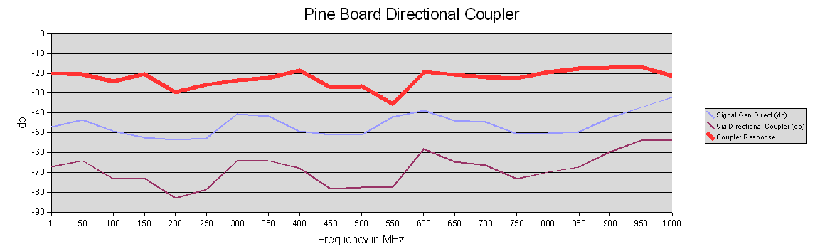
My initial test showed that it was about 20db down from 1.7mhz to 150mhz but that
was the limit of my signal generation at my QTH. I then went over to N0FP's QTH as
he owns a nice Wavetek signal generator that is good to 1ghz. We measured his signal
generator from 1mhz to 1ghz in 50mhz increments and then remeasured the same range
with the coupler inserted. This would allow us to calculate (approximately) how the
coupler performed over a wide frequency range


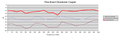
The coupler was generally 20db down... with a couple of blips at/near 30db down. (I
think that we might have an data error at 550mhz... but we are not sure and it is
not really an issue either way.) The coupler performs very well at HF-VHF. In fact
it is usable all the way to 1ghz.


I am going to build a final version of this coupler into a small Hammond box. As part
of that effort I will also minimize the wire lead lengths. Once that is done I plan
to visit N0FP and test the final product.


I am extremely happy with this experiment and plan to make the final version of this
(in the box) part of my permanent test gear for my spectrum analyzer along with my
step attenuator.  


73 de NG0R


By:
Category:
Comments Off

W7ZOI oscillator in KiCad


Tonight after the kids went to bed I whipped up this schematic in KiCad. (I put it
into TinyCad last night.)


My initial impression is that I can probably crank out a basic schematic quicker in
KiCad but I am not as happy with it. KiCad is pretty easy to layout some basic components
and add some wire links. I probably had the basic schematic done in 10-15 minutes.
I then spent another 30 minutes cleaning up with simple things like alignment. I think
that TinyCad has a much more professional look with the snap to grid function that
is on by default.


I also stumbled in KiCad with how to create a simple picture for the web. I ended
up printing the schematic to CutePDF. Once I had a PDF I adjusted the magnification
so that it looked good on the screen and the used SnagIt to grab a screen shot.


I still need to work through creating a Netlist, Partslist, and then trying to do
some parts placement on a PCB.


I am very unimpressed with the help file for KiCad so far compared to TinyCad and
FreePCB.


My initial feel is the KiCad is good for creating a quick schematic... but initially
I still prefer TinyCad+FreePCB. I will need to do some more testing to see how I feel
at the end of the process if I can get to the point where I am ready to etch a board.


-------------------

An update to this post.... the top section was a couple of hours ago....


I decided to continue to play with KiCad to see how the board layout, auto parts placement,
and router work.   After a LOT of messing around with the board layout program
I decided that you need to manually layout the parts, then compare it against the
auto placement, and then figure out what works best for each part. I then used the
auto router to figure out where to put the traces. It is uses the same auto router
as FreePCB.


The board below is what KiCad and the router think I should put together.


I have to say that for my first pass the schematic capture was decent... but the board
layout leaves a LOT to be desired. This board would not meet my needs and would not
be viable to etch at home.


Bottom Line:


Right now I would say that I probably will lean towards TinyCad + FreePCB as I could
crank out a workable PCB much quicker and with a more realistic layout. KiCad is installed
and will be my backup. Ideally I would like to be able to use both of them as needed
and figure out a way to convert the files between them... until then I will focus
on TinyCad+FreePCB.


By:
Category:
Comments Off

PCB Design

I spent some time
last night working on getting a schematic laid out in TinyCad.
I had a couple of issues that took me a little to resolve since it was my first time
laying something with it.  Getting my ground to work as an actual ground and
then I had a couple of components where the wires would not properly connect even
though the junctions were good.  I resolved all of the ground issues... and most
of the junction issues. I then exported it to a
netlist and
partslist.


Next I moved on
to FreePCB. I was able to import
my netlist and
partslist right way. I then updated the package/footprint info and then started doing
the parts placement. The couple of places where I had junction issues came back as
an issue. I ended up just deleting the network for that connection and manually connected
the parts. Once a person figures that out it is a quick fix. I then decided that I
wanted a two sided board so that it would work with the autorouter software. I then
created a dsn file. (I used generic pads for the toroid based transformer.)


Next I opened the
dsn file with the Autorouter software. It laid out the connections in a couple
of seconds. The problem is that four of the traces were on the bottom of the board
which is an issue when I want to work on a one sided solder mask. I then exported
my updated dsn file and exported my spectra file.


Next I went back
to FreePCB and opened my updated
DSN and spectra files. I discovered that I can click on the traces and change them
back to top layer. That is a very cool hack to make my simple board a single sided
board again... traces on top... ground on the bottom. I then exported the CAM files
so that I would have some Gerber files to work with.


Next I opened up Viewmate and
opened up my Gerber
files
. I was able to select my layer(s) and save them as BMPs or send them to
the laser printer or cutepdf. If I owned the app for the $49 I would have several other
options as well.


I probably spent
4 hours end to end for my first time through the process. I could have easily made
a working "print & peel" or if I had a flatbed inkjet printed directly on a board.
Granted that my schematic was pretty simple but the process would have worked.  
I
did quick measurements and the capacitors that I ordered would have fit the pad
foot print on my board.  The crystal pads should be adjusted to be a bit bigger
and the toroid pads probably should be spaced out a bit further as well.)


So overall I would
rate the experience as a B or B+ especially given that I am not an EE nor do
I have any experience with this kind of software or tools. (All of the software that I
used last night was open source or free.)


By:
Category:
Comments Off

Field Day antennas

For some reason I started searching for Field Day info and started looking at antennas again. I have some nice mono band wire dipoles that I built for the 2009 Field Day weekend. They play well but it does become a challenge to find enough trees in my campsites to hang all of them from.


I would like to find something simpler to operate 20-40-80.  Something like an
G5RV or End Fed might be options.


The G5RV for 80m is about 102' long.


The Par Electronics end-fed is another antenna that I hear a lot of QRP folks mention
with positive responses. The 10/20/40 is about 40' long.


At the end of the day it is all a comprise... but if I operate QRP (solo) I can't
afford too much loss as my signal is already pretty small. For 2010 my plans might
include having my two older sons with me operate as a multi-single style station which
would probably mean that I need to pull out my big radio and think about QRO ~ 100w
since they will probably want to operate SSB and I will probably end up filling in
on CW when they don't want to operate.


-----

More notes:

Great write up on home made end fed dipoles:  (You have to love the toroid based
transformer)

http://www.aa5tb.com/efha.html


By:
Category:
Comments Off

BASIC for the PIC (programming)

I am looking to do some programming on some PIC MCUs in the near future. I have two boards sitting around my office. One take a 9 pin serial and the other takes a USB. I am really not a Assembly or C developer and I am resistant to go down that path unless I am really in love with the platform.


A friend at work owns and recommends the Mikro line. I am in interested in Mikro and
Proton and think that Great Cow might be interesting just to see what it looks like.


Mikro Basic

http://www.mikroe.com/en/compilers/mikrobasic/pro/pic/


Proton PICBasic

http://www.picbasic.org/proton_development_suite.php


Great Cow Basic

http://gcbasic.sourceforge.net/index.html


PICBasic

http://www.melabs.com/products/pbc.htm


------

Here are some other links and notes that I dug up a couple of weeks ago:


Looks nice.. but it appears that new development is slowing down on this package

http://www.basicmicro.com/MBasic--PICmicro_c_49.html


Instruction manual:

http://www.basicmicro.com/downloads/docs/mbasic.pdf


BASIC example of writing to an LCD:

http://www.basicmicro.com/downloads/code/lcdwrite.bas


Might be work a look:

http://www.picbasic.org/


Tool Comparison:

http://www.picbasic.org/compiler_comparisons.php


Some people use this for a 18 series PIC.

http://www.sfcompiler.co.uk/swordfish/index.html


Another Basic tool:

http://melabs.com/products/index.htm


Basic compiler and simulator:

http://www.oshonsoft.com/pic.html


By:
Category:
Comments Off

Transistor Impedance (more)

Here are some low frequency examples:


Rc is the resistor at the collector   -   Re is
the resistor at the emitter


This model assumes that you are getting your RF from a tap between the collector and
collector resistor.


http://en.wikipedia.org/wiki/Common_emitter


I am still working on trying to figure out this impedance thing. N0FP added another
bit of complexity... what happens if you have a tank circuit vs. no tank circuit. 
... Argghhh.


I need to pull out SSDRA and do some more reading or re-reading as the case might
be.


By:
Category:
Comments Off

Transistor Impedance

I am trying to figure out how to calculate the input and output impedance for transistors. (Kind of an important detail when you are designing radio gear.)


The link below has some interesting examples. I grabbed some screen captures of them
in case they eventually fade away on the internet like so many good things do.


http://hyperphysics.phy-astr.gsu.edu/Hbase/Electronic/tranimped.html


The challenge that I have with these examples are that they appear to be DC values.
I live in an RF world which means we are talking about AC or even more complex is
DC & AC at the same time.

------

Here is another link that I like:

http://www.geofex.com/article_folders/impednc.htm


I have seen/read other examples like this where you roll up the values and get to
an approximate value.


This still bothers me.  Why is it so hard to figure it out?  We should be
able to calculate it and measure it. This feels kind of elusive and black boxish. 
....arghhh.