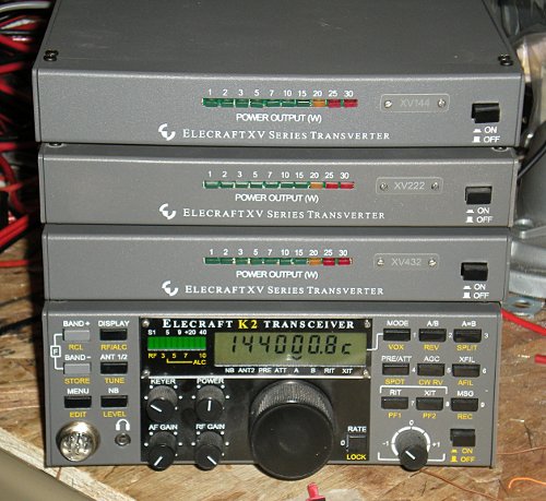
Elecraft Transverters
I decided to stop my tweaking and take some measurements in a slightly more scientific format. --aka... I was stumped and needed to noodle through my data and step away for a little bit.
The fields below that are yellow indicate that I don't trust the results of my oscilloscope. (It is an old slow 60 MHz scope so I am pushing my luck measuring the LO and Mixed values on the 222 and 432 transverters.)
All oscope values are with the probe @ x10 - K2 drive from the K2 display

Good news: The 2m transverter (XV144) is working good. I am seeing what I expect for power levels and it should be near it's final form.
Bad news: The 222 and 432 transverters need some help. I am not sure of the exact problem but I have two ideas to investigate:
1. Go back thru the filter adjustments. I think that I need more signal going into U6.
2. U6 - is it bad or not getting enough signal to do much real work?
73 de NG0R
PS... I need to go back to remeasure the power out of the XV144. I thought that I had a 50w slug in the bird 43... but I think that I actually had the 10w slug in there. --That will mean that my power is still pretty low but at least it is measurable. :-(
PPS... C53 in the bandpass filter was acting weird on the XV222. I found it while poking around with the oscope. I top soldered the joint and resolved that little issue.
PPPS... I tweaked up the power level on the XV222. It is still running less than QrpP levels. I am going to take a break for the evening and ponder this some more.
PPPPS... After some pondering and discussion with N0FP I think that I have a plan of next attack to diagnosis this issue. Notes to follow once I have time to revisit the work bench.

- I went back to each transverter and reset the PA bias to 20mV.
- I did not adjust any of the filters... good or bad... measured As-Is
- I measured each transverter with three different R22 values Full Counter Clockwise, Centered, and Full Clockwise. (R22 is a variable attenuator for the IF input.)
The fields below that are yellow indicate that I don't trust the results of my oscilloscope. (It is an old slow 60 MHz scope so I am pushing my luck measuring the LO and Mixed values on the 222 and 432 transverters.)
All oscope values are with the probe @ x10 - K2 drive from the K2 display
Good news: The 2m transverter (XV144) is working good. I am seeing what I expect for power levels and it should be near it's final form.
Bad news: The 222 and 432 transverters need some help. I am not sure of the exact problem but I have two ideas to investigate:
1. Go back thru the filter adjustments. I think that I need more signal going into U6.
2. U6 - is it bad or not getting enough signal to do much real work?
73 de NG0R
PS... I need to go back to remeasure the power out of the XV144. I thought that I had a 50w slug in the bird 43... but I think that I actually had the 10w slug in there. --That will mean that my power is still pretty low but at least it is measurable. :-(
PPS... C53 in the bandpass filter was acting weird on the XV222. I found it while poking around with the oscope. I top soldered the joint and resolved that little issue.
PPPS... I tweaked up the power level on the XV222. It is still running less than QrpP levels. I am going to take a break for the evening and ponder this some more.
PPPPS... After some pondering and discussion with N0FP I think that I have a plan of next attack to diagnosis this issue. Notes to follow once I have time to revisit the work bench.