By:
Category:
Comments Off

QRSS Prototype

I finally got around to applying power to the prototype this afternoon.

I did not spend a lot of time but here is what I recorded in about 20 minutes of bench time:

I did not test it with a PIC, but I instead used the header pins.

Specs:
  • 12vdc  @.34amp
  • 26dBm or about 400mW of RF @ 10,140,030MHz
  • All harmonics are at least 47db down

Good: 
  • It made a LOT of RF
  • It was extremely clean
  • It starts up reliably

Bad or unclear:
  • It does not appear that my frequency shift with the second variable capacitor is working
Original Design Notes: /blog/2010/07/25/latest-qrss-pcb/

I will need to spend some more time with it when time permits... need to run off to dinner with my family.

73 de NG0R

By:
Category:
Comments Off

Camera Intervalometer

Here is a project that I have pend thinking about building using a PIC.  This designer used an AVR but almost any processor could handle this task.

http://kalshagar.wikispaces.com/ardTimeLapse


The pin out for the plug is pretty simple.  When time permits I will have to throw some parts on a bread board. I will likely used some fixed time values that are selectable vs. using pots.


By:
Category:
Comments Off

QRSS Prototype


Here is the prototype with the parts installed. Some time this week I would like to apply power to it. I can test it with the two header pins in place of the 16F628A. That should let me tune up the oscillator and the fsk shift with the two variable capacitors. 

I have some existing QRSS code that should be pretty easy to port. I think that I will just need to update the pins that I decided to use. (My existing code is setup to echo the message and status on the LCD display. For simplicity with the initial prototype I decided to leave out the LCD.)

I have a couple of  additional features that I am pondering adding to the design. Parts count/price + available memory will be a couple key considerations.

73 de NG0R

By:
Category:
Comments Off

Latest QRSS PCB

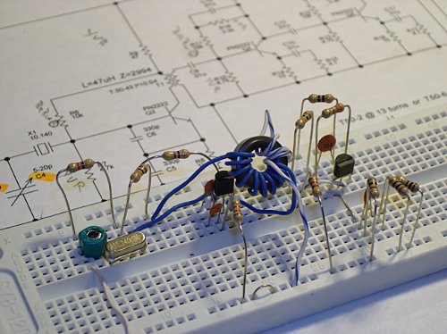
Here is another QRSS prototype that I am working on. This one will support standard single frequency and dual frequency CW. (I will add FSK in a future version of the board.) The design will use a PIC 16F628A for the keying.  It is likely that I will need an additional amplifier stage but I want to assemble and measure this prior to adding too many more features. (It is easier to debug & test this if I control how much change I introduce in each version of the prototype.)

Click on the image to see a larger version of the schematic.


I then exported the TinyCad schematic into FreePCB to layout the board (below). 


I then exported the board layout into the appropriate Gerber and PNG formats.


I then printed the artwork on some blue print and peel paper with my laser printer and then taped it to the 3x4 inch piece of single sided circuit board.


I then ran the combo through my modified laminator to transfer the laser toner to the circuit board. Four passes through the laminator is enough to bond the toner.


I then drop the combo into a container of water. After about 60 seconds the blue print and peel is ready to remove from the board. Once the board is dry I then applied some green foil to the PCB to seal the toner. (This is the first time that I have tried the the green foil.  It was a mixed success... it actually reduced the quality of the PCB because the traces were not as clean as the raw toner was.  --Live and learn.)


Since it is summer time I decided to etch the board in the garage to reduce the fumes. I have a make-shift table setup on two saw horses. I poured about 1/2 a quart of homebrew etchant into a one gallon plastic container. (The container is a $2 piece of tupperware from Walmart.... great for etching boards.)


I placed the board into the etchant for about 10-15 minutes. I agitated the container about every 3-4 minutes with a quick swirl motion. 


After the copper was dissolved I used some rubber gloves to pick up the board and transfer it to a container of water to rinse it off.  The copper is green in this picture because the green foil sealer is still on the board.


I then rinsed the board with some Acetone which dissolved the foil and laser toner.


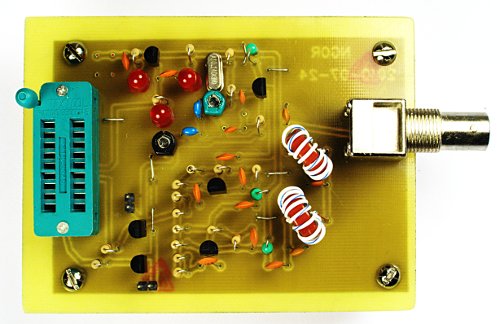
I then drilled the holes with a Dremel press and some #67 drill bits.  I used some slightly larger bits for the ZIF and BNC connectors.


I will try to get the parts stuffed and soldered down Monday night. After that I should be able to measure the power and validate that the harmonics are down at least 43db.

This is not the best board that I have etched so I would only rate it about a 7 out of 10 because of the green foil.

It is the most complex that I have tried etch because it was originally designed a dual sided PCB. The ZIF and BNC provided a couple of initial challenges but I think that I have solved those as well.

This has been a very enjoyable project... lots of learning and challenges.

73 de NG0R

By:
Category:
Comments Off

Wall Cloud


Here is a picture of a wall cloud in Kingston, MN taken on 7/17/2010

The group of amateur radio operators in Meeker Co activated Skywarn for the weather service three times on Saturday between 1pm and 11pm.  That made for a long day watching the skies


By:
Category:
Comments Off

Ubuntu & JNLP

I wanted to see if I could run WeatherTap   http://www.weathertap.com/ on a Linux machine. It appears that it is designed to run on Windows but it is Java based so it should be portable. My home PC is running Ubuntu 10.4 LTS 64bit.  AMD64 is the magic in this story.

When I try to launch the radar image it gives to a XYZ.jnlp file which is supposed to open up in the Java Web Start engine. My 64bit machine did not know how to handle this file extension and when I tried to manually launch the Java Web Start engine it returned an error.

After a bunch of searching I found some helpful hints at:
http://dmartin.org/weblog/running-java-web-start-apps-ubuntu-linux-amd-64

Steps:
    $ sudo apt-get install ia32-sun-java6-bin

    $ sudo gedit /usr/bin/javaws

I commented all with # at the beginning of each line and added at the end:

    /usr/lib/jvm/ia32-java-6-sun/bin/javaws $1

Save the file and then launch Firefox and you should now be prompted for what to use to open the jnlp file. Choice the proper Java option from the menu and you should be in business.


By:
Category:
Comments Off

Giligan's Island and a new generation


This afternoon I was talking with Jacob (11), Ben (9), and Joe (7) and for some reason the topic of Giligan's Island came up. I did not realize that they did not know what I was talking about.

I took a random stab at the internet and went over to Hulu.com and sure enough they had a link to it over at The WB. The humor from 1964-1967 is still just as funny now. I remember watching these in syndicated reruns as a kid. (They were old back then.)

http://www.hulu.com/search?query=Gilligan%27s+Island&st=0

Here is a nice link to the Wikipedia article about the show:
http://en.wikipedia.org/wiki/Gilligan%27s_Island


Shortly after that we started watching Magnum PI on Hulu.  Now that I know that it they have Magnum I might have to catch the episodes that I am missing. --Great show!


By:
Category:
Comments Off

Sunday night breadboard


Tonight I worked on laying out breadboard for the QRSS rig while talking on Echolink on the QRP conference.

I had wanted to etch a board but the last couple of days have been pretty busy. Tonight was the first time that I have actually played with the radios (outside of skywarn) or visited my electrical workbench for an RF project.

I decided to lay out the oscillator + PA + lowpass filter so that I could validate the combined design and then focus on using the PIC 16F628 for PWM (pulse width modulation) with a LED acting as a varactor diode. I finished the oscillator + 1/2 of the PA. It was fun to get back to the work bench for a little while.

73 de NG0R