By:
Category:
Comments Off

SO2R box from K1XM

SO2R = Single operator two radio


While my interest
my hard core contesting has diminished over time and as I become more committed to
building & testing I still enjoy some of the innovation that comes from the contest
community. The K1XM box is kind of neat. The K1XM box is need because they are trying
to establish a open source protocol/standard for how to talk to this type of interface
box.


http://www.k1xm.org/SO2R/index.html


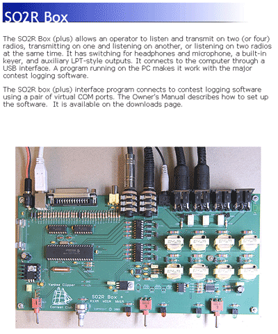
The image & text is from the K1XM web page... go visit... it
is good reading.


I have been pondering building own mic, key,
speaker, etc kind of relay/switch box for more than a year based upon of of own requirements.
My box is just a concept with the details written down in my "idea book." For now
(ok... back in December 2009) I decided to reduce the amount of clutter on my desk
by focusing my primary station on my Icom
IC-756
, Elecraft K2 and
a Small Wonder Labs PSK Warbler
for 80m.


Eventually I will probably build a matrix switching box but it will be a little ways
down the road. It is fun to read about how other people solve these types of problems
in the mean time.


By:
Category:
Comments Off

30m Oscillator (Night 5)

I was not happy with the power levels from the RF gain stages. So last night I started slowly tweaking them until I decided to remove them and come up with another plan.


It will not likely put out this kind of power
at these levels... but it is a learning tool to figure out what is going on.


For tonight (time permitting after the family responsibilities) I think that I am
going to build a simple test fixture and use my signal generator to drive it with
a 0 dBm source. I did some modeling of the NPN at different bias levels. In my original
testing I was noticing some clipping of the sine wave on the oscope which looks like
I was running out of current on the negative peak. I would like to drive more gain
in the class A stage and maintain a healthy sine wave in this early stage.


I am hopping that I can use the test fixture to try to drive the NPN much harder and
get some gain out of this part. (Granted that the PN2222 is not a spectacular component
but I am well within it's rated power levels.) Originally I was trying to be too safe
and the result was low power levels. I will try to spank it a bit to see what happens.
(The PN2222 are cheap parts so I can afford to let the smoke out of a couple of them
if needed.)


By:
Category:
Comments Off

30m Oscillator (Night 4)

I found some bench time after the family shared a movie Saturday night and went to bed.


I did a bunch of testing and made some changes.


  • I tweaked the gain stages slightly. Q3 and Q4 seem to operate more efficiently with
    a 100 ohm resistor instead of the 10 ohm resistor. I validated both values with the
    spectrum analyzer and I got a bit more gain of the fundamental frequency and less
    impact on the harmonic frequencies.


  • In talking with N0FP earlier in the day I discovered that my output at 50 ohms was
    loading the final transistor. I played with using a matching transformer but was unhappy
    with the result. (I think that I was getting tired and should retest the process with
    the transformer again.)


  • I also tried changing the output from a common-emitter to a common-collector. The
    common-collector design has a lower output impedance and was a better match to the
    50 ohm load. It was a not a perfect match @ 4:1 but it was pretty decent and reduced
    the amount of loading. (In the end I left it as a common-emitter design for now.)


  • I then relocated the low pass filter from after Q2 to it's new home after Q4. I tried
    using a 4:1 transformer from the collector to the input of the filter but was running
    into some flaky issues. I experimented again with common-emitter vs. common-collector
    to try to get a better match. In the end the common-emitter design worked pretty well
    so I left it alone.


Results:


  • Power is now running about  3.2mW or ~ +5dBm. (I referenced the spectrum analyzer
    against my signal generator and then compared the final output of the transmitter.)


  • My harmonics are down 55dB against the fundamental frequency. (It would be legal to
    put on the air as is.)


Next steps:


  • Look at some more options to increase the power into the 100-200mW range.


  • Add a key (RCA or 1/8" jack) so that I can try to make a QSO with it.


By:
Category:
Comments Off

Mid Winter Madness (St Cloud Hamfest)

Ben (KD0JZK) and I (NG0R) went to the hamfest this morning.


I think that we got the steal of the show. We bought a bunch of bags of small &
medium sized variable capacitors. These will make excellent  tuners for some
of the simple rigs that I am building. In many cases I just need the VXO is just needed
to get the rig dialed into the proper sub band near the crystal frequency.   --
All of the parts in the picture came to a grand total of $4.00.


I also bought a log book for Jacob and one for Ben. I have using a spreadsheet printed
out to paper so far for them until we picked up the log books. At some point maybe
we will think about computer logging... but that is a LONG ways off for them. 
:-)


I also picked up Experimental Methods in RF Design. It is the informal follow-up/successor
for the 1977 Solid State Design for the Radio Amateur.  It has been on my hit
list for a couple of years but I have been unable to part with the money. Being able
to see them and compare them convinced me that it was worth the investment.


73 de NG0R


By:
Category:
Comments Off

30m Oscillator (Day 4)

I am a little behind on posting so I am going to try to get caught up before I visit the work bench again.  :-)


Last night Jacob (KD0JZJ), Ben (KD0JZK), and I (NG0R) attended the W0CRC monthly
club meeting in Hutchinson, MN. Roger (K0RTR) and Roger (W0DEU) did a presentation
about NVIS antennas for 75m and also talked about simple wire antennas for camping
and out of town trips. We had some conversations about how 17m is a neat rag chew
kind of band.


Jacob and Ben got meet Devin KD0JHP who is a 12 year old ham that lives in the Hutchinson
area. It was fun to be able to get the kids together with some peers their own age.  
:-)


I like to bring some sort of in-flight project that I am working on. It is my personal
effort to show that there is more to the hobby than just the commercial appliance
approach to the hobby for those that might be interested in building stuff. (I own
several appliance rigs... but I get the most enjoyment out of the gear that I either
built myself or that I did some interesting integration with.) The hobby is different
to each person so it is fun to share some other points of view.


Thursday night & Friday over lunch I converted the 30m project from the bread
board over to a copper board. In the process I added a couple more gain stages.


I might have gotten a little crazy.


When I updated the schematic for this I was seeing some low/marginal

gain so I added to gain stages with the idea that I would tweak them on

the board so I could work out the details and measure it.


I was not happy with the power at any of the stages on the copper board. I consulted
with N0FP and we decided that I was being too conservative with Q2, Q3, and Q4 and
that I needed to let some more current flow and get some gain. Changing the collector
resistor from 470 to 220 ohms and the emitter resistor from 200 to 10 ohms really
made a big change. (I am now feeling some heat dissipation from the collector resistors
and the NPNs... they are not hot... but on the upper end of warm.)


I need to go back an re-evaluate if I need this many gain stages with this part. I
was in a hurry over lunch on Friday so I did not have time to make as many detailed
measurements as I might like.. but I am not seeing any gain in Q4.. and I am not sure
about Q3. It is possible that i might have exceeded the limits of these simple NPN
parts. I am going to measure each stage on the oscope and if needed lift the feed
to each stage and measure them on the spectrum analyzer. If I exceeded the part specs
it is possible that I am just adding harmonics in the NPN as I hit it too hard.


Depending on how things look and measure out I will likely end up moving the low pass
filter around once I figure out how many gain stages that I need during this round
of testing.


This is also making me think that I need to build a simple test fixture and use the
signal generator to test one or two stages and see where the upper limits of the part
are.


I would like to sneak in a little bit of bench time Saturday night or Sunday morning.
This weekend is pretty busy with events and chores so bench time will be pretty limited.


73 de NG0R


By:
Category:
Comments Off

PCB Etching

I just saw some good info on PCB etch for the homebrew
folks and thought that it was worth putting up on the blog.


http://www.pulsarprofx.com/PCBfx/main_site/pages/start_here/index.html


A nice site that
discusses how to do this and where to get the stuff. There has been quite a bit of
chatter about using laminating stations for the thermal transfer.


Search for "GBC
laminator" on eBay and you should find it.


The rumor is that the GBC laminator is good for .032 boards with one pass through
the heater. I will need to order some transfer paper and some etchant. I am enjoying
making boards at home with pads and islands but some days I would also like to have
the sharp/clean/dense boards that you can get when you lay them out in software and
then use the laser printer.


By:
Category:
Comments Off

Island Construction

Tonight I started to layout a board for my 30m transmitter project.


I updated my schematic to include a couple more gain stages. I then grabbed a piece
of copper circuit board and started to map out where the parts were going to go. I
left room for a bracket and BNC on one edge and then on another edge I left room for
a variable cap & bracket + something to hold a 1/8" or RCA jack for the CW key.


I drew it out in pencil and then used a Sharpie marker to make the notes more readable
once I felt ok with the parts placement. I borrowed a Dremel drill press from N0FP
earlier this afternoon. I used a NJ pad cutter to make the isolated islands on the
board. (A few extra RPMs are your friend with the dremel & press so that cutter
does not try to walk or jump around. I figured this out about 12 pads into the project.)
Once the islands were cut I tinned the islands to make them easier to work with.


Since this is a learning experience I am trying to leave room incorporate changes
as I come across them. (Gain & filtering are likely additions.) I am looking forward
to morphing the breadboard into a copper board with solder connections and then hooking
it up to the test gear.


The island cutter was a lot of fun. I like this as a tool to build some quick circuits.
I think that I will need to purchase a another Dremel and a matching press when the
right opportunity comes along.


73 de NG0R


PS...  Someone asked for more info on how this works


I bought the tool from:

http://www.njqrp.org/islanderpadcutter/index.html


Here is an illustration of how it works:


(illustrations shown above, and liberally used in the instruction sheets
shipped with the pad cutters, were graciously supplied by master graphic artist Paul
Harden, NA5N)


The NJQRP no longer sells these kits. (I have three of them.)


You can buy a similar version from Dan's Small Parts:

http://www.danssmallpartsandkits.net/


http://www.danscloseoutsandspecialdeals.com/Dansspecialdealsno3.html


Be aware that Dan's cutter is designed to fit into a drill press... not a Dremel.


By:
Category:
Comments Off

Java Circuit Simulator

This is pretty cool:   http://www.falstad.com/circuit/


While this is not a detailed as something like LTSpice (which is very cool) this is
very useful. While I am not sure if I can get it to simulate HF/VHF frequencies there
a lot things that you can simulate at lower frequencies.  You can run this within
your browser if don't want to save it locally.


You can draw out a schematic from scratch or use some of the existing template circuits.


PS... Updated post....


Paul sent me a response this morning to a question about how to scale this into the
HF frequency range.


I am tweaking a simple NPN Common-Emitter follower circuit shown below.


(yes... I know that the picture says 10.1mHz instead of 10.1MHz...
I figured it out after I grabbed the image.)


Go the menu and select options.... other options.

You should see the window below. I changed my "time step size" to 100p. (10p might
give a nicer sine wave depending on what you are looking at.)


Next I edited the value for the signal source. I changed it to: 10.138MHz which will
show up as 10.1MHz


Very cool stuff. I will have to play with the later. It might be an interesting way
to look at Class A vs AB vs B vs C amplifiers in quick fashion. (I don't use LTSpice
enough to quick in setting up simulations especially between AC & DC analysis.)


By:
Category:
Comments Off

30m Oscillator (night 4)

I made a few changes tonight and feel pretty positive about the limited time that I had to work on it.


Today's notes:


  • I removed the tank circuit and replaced it with a resistor on the collector of Q1.
    (The oscillator should now be a wide band design for future projects.)


  • I re-biased Q2. (This morning before work I built a spreadsheet that helped me better
    understand the values of the components and the impact on the transistor.)


  • The loudest harmonics are now about 42dBm down. (The two loudest are the 6th &
    7th harmonics.)


  • The power at the output of the filter is about -10 dBm or .1mW


  • I updated the schematic with the changes.


Next steps:


  • Move this to a copper board with islands or Manhattan pads


  • Design an additional gain stage (or two)


  • Research "class AB" and "class C" amp options