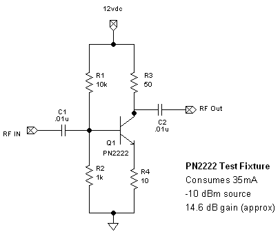
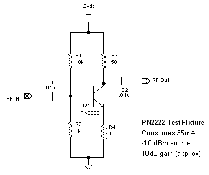
By:
Category:
Comments Off

Push-pull amp

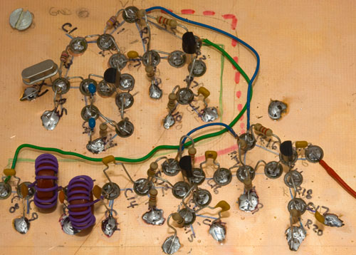
I have some push-pull questions so I am going to build a model something like this:


I want to play with a simple push-pull NPN amplifier running in class AB.  I
have big stash of PN2222 so I want to use it because it is on hand. (I know that it
is a crummy RF part... but this is an R&D activity for some personal growth...
I will move on to real parts once I have a bit more experience.)


PS... the I have posted some updates in red to my own
questions below.


Q1. What size inductor do I need for L1?

In this phase L1 is not critical to choke the RF from the
power supply.


If you use an inductor, pick a value that is going to be at least 150 XL ohms at the
lowest frequency and a self resonant frequency higher than the highest frequency you
intend to use.


Q2. I would guess that L1 could be replaced with a resistor since it is really controlling
the current at the collectors.   I need to understand why the example has
an inductor in there since it is not a tuned circuit.

150 ohm resistor would probably be fine.


If you use an inductor, pick a value that is going
to be at least 150 XL ohms at the lowest frequency and a self resonant frequency higher
than the highest frequency you intend to use.


Q3. How do I determine the output impedance? (It might be helpful to know if I want
to feed a 50 ohm filter.)

In theory it should look something like:


Hmmm... more reading before I can visit the work bench.


By:
Category:
Comments Off

30m Oscillator (Night 7)

My Boonton 4200 power meter showed up today.


I went back and remeasured the circuit on the meter. I originally thought that I was
getting 10-12 dB of gain. With the Boonton I am measuring about 14.6dB of gain from
the circuit with about 35mA of consumed power.


I tried several PN2222 components and the range was all over the board. Gain was pretty
close but the power consumed was pretty wild by a factor of 3x. (I threw the the ultra
wild part away.) I also substituted a 2N3904 into the circuit. It had almost exactly
the same gain and power consumption model.


It seems like I should be able to get this much gain with 1/3 of the power consumption.
I am not sure how to do that as balancing the base against the emitter and collector
for peak gain and minimal consumption is pretty challenging. I suspect that I can
tweak the resistors a bit more but this would be easier with a dual channel power
supply with digital feedback to rough out the voltage and current values while watching
on the oscope & power meter.


---Hmmm I am still kicking myself for not buying that bench power supply that I was
eyeing during the hamfest last Saturday. I might have to resolve that via eBay or
the up coming  Midwinter Madness hamfest in Buffalo.


By:
Category:
Comments Off

NPNs for making power

I looked up what the Elecraft folks are using in their K2 to create RF at some real levels. (I love my K2.)


PreDriver: 2N5109 ($1.87 at Mouser)


Driver: 2SC2166 ($3.95/12.70 at RF Parts)

-- The 2SC2166 is rated for 3-4 watts of power at HF freqs


Finals: 2SC1969 ($9.95 at RF Parts)

-- Running a push-pull pair

-- The 2SC1969 is rated for 10-14 watts in class AB.

-- I can confirm that a 2SSC1969 is good for 7-10 watts running by it's self.


My K2 will generate 10-14 watts of power with 2-3 amps of power. At rest it draws
about 300mA.


Interesting stuff as I work thru how to make some RF power.  I will have
to search on eBay for some of these parts as the high end parts are probably a buck
a piece or so compared to the normal sources.


By:
Category:
Comments Off

30m Oscillator (Night 6)

Last night I was messing with the modeling tools and getting weird answers that did not make sense. Ultimately it was time to go to the bench and put some parts on the breadboard.


Initially I stated out with with the values listed in night 5 schematic. I was not
happy with the power levels. I chatted with N0FP a bit and we came up with some different
values to push up the gain. That presented a new issue... my circuit got hungry. At
one point it was consuming 131mA to get 18dB of gain.  N0FP suggested that maybe
I should put my circuit on a diet.


After pondering this a bit I changed the values to those listed on the schematic/picture
above. Now I am getting 10dB of gain and consuming 35mA of power. This is better but
still seems kind of hungry for the power levels that I am creating in class A.


I would like to see 10dB of gain at 6mA. I will need to ponder this some more. It
might also be time to grab a 2N3904 and compare the results against the PN2222.


Lots of learning going on... slowly moving the ball forward.


By:
Category:
Comments Off

SO2R box from K1XM

SO2R = Single operator two radio


While my interest
my hard core contesting has diminished over time and as I become more committed to
building & testing I still enjoy some of the innovation that comes from the contest
community. The K1XM box is kind of neat. The K1XM box is need because they are trying
to establish a open source protocol/standard for how to talk to this type of interface
box.


http://www.k1xm.org/SO2R/index.html


The image & text is from the K1XM web page... go visit... it
is good reading.


I have been pondering building own mic, key,
speaker, etc kind of relay/switch box for more than a year based upon of of own requirements.
My box is just a concept with the details written down in my "idea book." For now
(ok... back in December 2009) I decided to reduce the amount of clutter on my desk
by focusing my primary station on my Icom
IC-756
, Elecraft K2 and
a Small Wonder Labs PSK Warbler
for 80m.


Eventually I will probably build a matrix switching box but it will be a little ways
down the road. It is fun to read about how other people solve these types of problems
in the mean time.


By:
Category:
Comments Off

30m Oscillator (Night 5)

I was not happy with the power levels from the RF gain stages. So last night I started slowly tweaking them until I decided to remove them and come up with another plan.


It will not likely put out this kind of power
at these levels... but it is a learning tool to figure out what is going on.


For tonight (time permitting after the family responsibilities) I think that I am
going to build a simple test fixture and use my signal generator to drive it with
a 0 dBm source. I did some modeling of the NPN at different bias levels. In my original
testing I was noticing some clipping of the sine wave on the oscope which looks like
I was running out of current on the negative peak. I would like to drive more gain
in the class A stage and maintain a healthy sine wave in this early stage.


I am hopping that I can use the test fixture to try to drive the NPN much harder and
get some gain out of this part. (Granted that the PN2222 is not a spectacular component
but I am well within it's rated power levels.) Originally I was trying to be too safe
and the result was low power levels. I will try to spank it a bit to see what happens.
(The PN2222 are cheap parts so I can afford to let the smoke out of a couple of them
if needed.)


By:
Category:
Comments Off

30m Oscillator (Night 4)

I found some bench time after the family shared a movie Saturday night and went to bed.


I did a bunch of testing and made some changes.


  • I tweaked the gain stages slightly. Q3 and Q4 seem to operate more efficiently with
    a 100 ohm resistor instead of the 10 ohm resistor. I validated both values with the
    spectrum analyzer and I got a bit more gain of the fundamental frequency and less
    impact on the harmonic frequencies.


  • In talking with N0FP earlier in the day I discovered that my output at 50 ohms was
    loading the final transistor. I played with using a matching transformer but was unhappy
    with the result. (I think that I was getting tired and should retest the process with
    the transformer again.)


  • I also tried changing the output from a common-emitter to a common-collector. The
    common-collector design has a lower output impedance and was a better match to the
    50 ohm load. It was a not a perfect match @ 4:1 but it was pretty decent and reduced
    the amount of loading. (In the end I left it as a common-emitter design for now.)


  • I then relocated the low pass filter from after Q2 to it's new home after Q4. I tried
    using a 4:1 transformer from the collector to the input of the filter but was running
    into some flaky issues. I experimented again with common-emitter vs. common-collector
    to try to get a better match. In the end the common-emitter design worked pretty well
    so I left it alone.


Results:


  • Power is now running about  3.2mW or ~ +5dBm. (I referenced the spectrum analyzer
    against my signal generator and then compared the final output of the transmitter.)


  • My harmonics are down 55dB against the fundamental frequency. (It would be legal to
    put on the air as is.)


Next steps:


  • Look at some more options to increase the power into the 100-200mW range.


  • Add a key (RCA or 1/8" jack) so that I can try to make a QSO with it.


By:
Category:
Comments Off

Mid Winter Madness (St Cloud Hamfest)

Ben (KD0JZK) and I (NG0R) went to the hamfest this morning.


I think that we got the steal of the show. We bought a bunch of bags of small &
medium sized variable capacitors. These will make excellent  tuners for some
of the simple rigs that I am building. In many cases I just need the VXO is just needed
to get the rig dialed into the proper sub band near the crystal frequency.   --
All of the parts in the picture came to a grand total of $4.00.


I also bought a log book for Jacob and one for Ben. I have using a spreadsheet printed
out to paper so far for them until we picked up the log books. At some point maybe
we will think about computer logging... but that is a LONG ways off for them. 
:-)


I also picked up Experimental Methods in RF Design. It is the informal follow-up/successor
for the 1977 Solid State Design for the Radio Amateur.  It has been on my hit
list for a couple of years but I have been unable to part with the money. Being able
to see them and compare them convinced me that it was worth the investment.


73 de NG0R


By:
Category:
Comments Off

30m Oscillator (Day 4)

I am a little behind on posting so I am going to try to get caught up before I visit the work bench again.  :-)


Last night Jacob (KD0JZJ), Ben (KD0JZK), and I (NG0R) attended the W0CRC monthly
club meeting in Hutchinson, MN. Roger (K0RTR) and Roger (W0DEU) did a presentation
about NVIS antennas for 75m and also talked about simple wire antennas for camping
and out of town trips. We had some conversations about how 17m is a neat rag chew
kind of band.


Jacob and Ben got meet Devin KD0JHP who is a 12 year old ham that lives in the Hutchinson
area. It was fun to be able to get the kids together with some peers their own age.  
:-)


I like to bring some sort of in-flight project that I am working on. It is my personal
effort to show that there is more to the hobby than just the commercial appliance
approach to the hobby for those that might be interested in building stuff. (I own
several appliance rigs... but I get the most enjoyment out of the gear that I either
built myself or that I did some interesting integration with.) The hobby is different
to each person so it is fun to share some other points of view.


Thursday night & Friday over lunch I converted the 30m project from the bread
board over to a copper board. In the process I added a couple more gain stages.


I might have gotten a little crazy.


When I updated the schematic for this I was seeing some low/marginal

gain so I added to gain stages with the idea that I would tweak them on

the board so I could work out the details and measure it.


I was not happy with the power at any of the stages on the copper board. I consulted
with N0FP and we decided that I was being too conservative with Q2, Q3, and Q4 and
that I needed to let some more current flow and get some gain. Changing the collector
resistor from 470 to 220 ohms and the emitter resistor from 200 to 10 ohms really
made a big change. (I am now feeling some heat dissipation from the collector resistors
and the NPNs... they are not hot... but on the upper end of warm.)


I need to go back an re-evaluate if I need this many gain stages with this part. I
was in a hurry over lunch on Friday so I did not have time to make as many detailed
measurements as I might like.. but I am not seeing any gain in Q4.. and I am not sure
about Q3. It is possible that i might have exceeded the limits of these simple NPN
parts. I am going to measure each stage on the oscope and if needed lift the feed
to each stage and measure them on the spectrum analyzer. If I exceeded the part specs
it is possible that I am just adding harmonics in the NPN as I hit it too hard.


Depending on how things look and measure out I will likely end up moving the low pass
filter around once I figure out how many gain stages that I need during this round
of testing.


This is also making me think that I need to build a simple test fixture and use the
signal generator to test one or two stages and see where the upper limits of the part
are.


I would like to sneak in a little bit of bench time Saturday night or Sunday morning.
This weekend is pretty busy with events and chores so bench time will be pretty limited.


73 de NG0R