By:
Category:
Comments Off

PCB Etching

I just saw some good info on PCB etch for the homebrew
folks and thought that it was worth putting up on the blog.


http://www.pulsarprofx.com/PCBfx/main_site/pages/start_here/index.html


A nice site that
discusses how to do this and where to get the stuff. There has been quite a bit of
chatter about using laminating stations for the thermal transfer.


Search for "GBC
laminator" on eBay and you should find it.


The rumor is that the GBC laminator is good for .032 boards with one pass through
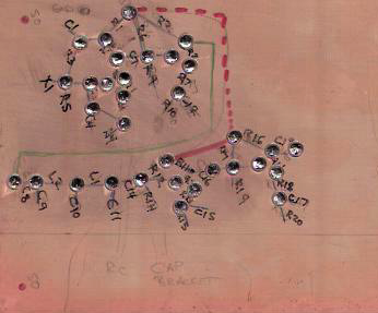
the heater. I will need to order some transfer paper and some etchant. I am enjoying
making boards at home with pads and islands but some days I would also like to have
the sharp/clean/dense boards that you can get when you lay them out in software and
then use the laser printer.


By:
Category:
Comments Off

Island Construction

Tonight I started to layout a board for my 30m transmitter project.


I updated my schematic to include a couple more gain stages. I then grabbed a piece
of copper circuit board and started to map out where the parts were going to go. I
left room for a bracket and BNC on one edge and then on another edge I left room for
a variable cap & bracket + something to hold a 1/8" or RCA jack for the CW key.


I drew it out in pencil and then used a Sharpie marker to make the notes more readable
once I felt ok with the parts placement. I borrowed a Dremel drill press from N0FP
earlier this afternoon. I used a NJ pad cutter to make the isolated islands on the
board. (A few extra RPMs are your friend with the dremel & press so that cutter
does not try to walk or jump around. I figured this out about 12 pads into the project.)
Once the islands were cut I tinned the islands to make them easier to work with.


Since this is a learning experience I am trying to leave room incorporate changes
as I come across them. (Gain & filtering are likely additions.) I am looking forward
to morphing the breadboard into a copper board with solder connections and then hooking
it up to the test gear.


The island cutter was a lot of fun. I like this as a tool to build some quick circuits.
I think that I will need to purchase a another Dremel and a matching press when the
right opportunity comes along.


73 de NG0R


PS...  Someone asked for more info on how this works


I bought the tool from:

http://www.njqrp.org/islanderpadcutter/index.html


Here is an illustration of how it works:


(illustrations shown above, and liberally used in the instruction sheets
shipped with the pad cutters, were graciously supplied by master graphic artist Paul
Harden, NA5N)


The NJQRP no longer sells these kits. (I have three of them.)


You can buy a similar version from Dan's Small Parts:

http://www.danssmallpartsandkits.net/


http://www.danscloseoutsandspecialdeals.com/Dansspecialdealsno3.html


Be aware that Dan's cutter is designed to fit into a drill press... not a Dremel.


By:
Category:
Comments Off

Java Circuit Simulator

This is pretty cool:   http://www.falstad.com/circuit/


While this is not a detailed as something like LTSpice (which is very cool) this is
very useful. While I am not sure if I can get it to simulate HF/VHF frequencies there
a lot things that you can simulate at lower frequencies.  You can run this within
your browser if don't want to save it locally.


You can draw out a schematic from scratch or use some of the existing template circuits.


PS... Updated post....


Paul sent me a response this morning to a question about how to scale this into the
HF frequency range.


I am tweaking a simple NPN Common-Emitter follower circuit shown below.


(yes... I know that the picture says 10.1mHz instead of 10.1MHz...
I figured it out after I grabbed the image.)


Go the menu and select options.... other options.

You should see the window below. I changed my "time step size" to 100p. (10p might
give a nicer sine wave depending on what you are looking at.)


Next I edited the value for the signal source. I changed it to: 10.138MHz which will
show up as 10.1MHz


Very cool stuff. I will have to play with the later. It might be an interesting way
to look at Class A vs AB vs B vs C amplifiers in quick fashion. (I don't use LTSpice
enough to quick in setting up simulations especially between AC & DC analysis.)


By:
Category:
Comments Off

30m Oscillator (night 4)

I made a few changes tonight and feel pretty positive about the limited time that I had to work on it.


Today's notes:


  • I removed the tank circuit and replaced it with a resistor on the collector of Q1.
    (The oscillator should now be a wide band design for future projects.)


  • I re-biased Q2. (This morning before work I built a spreadsheet that helped me better
    understand the values of the components and the impact on the transistor.)


  • The loudest harmonics are now about 42dBm down. (The two loudest are the 6th &
    7th harmonics.)


  • The power at the output of the filter is about -10 dBm or .1mW


  • I updated the schematic with the changes.


Next steps:


  • Move this to a copper board with islands or Manhattan pads


  • Design an additional gain stage (or two)


  • Research "class AB" and "class C" amp options


By:
Category:
Comments Off

30m Oscillator - almost a transmitter (night 3)

I finally got back
to the bench a week after after my last visit to the breadboard.


Don't even ask how I got to the bias values for Q2 as I tried so many
different things tonight that I am not even sure... this what the board had when I
unplugged it and called it a night.


Positive news:


  • I
    figured out the issue with the filter and the harmonics not being rejected. It turned
    out that the ground side of the BNC on the breadboard was not making a good connection.
    I moved the wire to a new location to make it easier to connect some test probes and
    that resolved it. If I was doing this Manhattan style it would not have been an issue. 
    :-)


  • The harmonics are down
    18db without the filter and 52db with the filter. The filter is providing 34db of
    suppression which is almost exactly what the model suggests that it should do.


  • If were going to put
    this on the air it would be legal. I think that the harmonics need to be down 43db
    and I am beating that with the low pass filter + tank circuit.


Less than positive
news:


  • I am not getting jack
    for gain from Q2 at the moment. I can't really measure power very well since I don't
    have a RF power meter in this power range. (I am working on that via eBay.)
    I went to the oscope and measured the base and collector of Q2 on channels A &
    B and it suggests that I am seeing about +25mV of gain peak to peak.


A bonus:


  • I
    was able to make it into a VXO!
     
    -----Since it was pretty
    stable I decided to grab a variable cap from the one of the junk boxes under the bench.
    I connected it from the Q1 emitter (before the Q1e to R4 connection) and the
    other side to ground.  Sure enough I can swing the frequency.  I can move
    it from 10,138,400 to 10,170,000.   At 10.170 the cap measured about 150pF. 
    If I was really going to do something like this I would put it on the board (without
    long alligator leads) and remove the tank circuit on the collector. The variable cap
    impacts the tuning on the tank circuit and also pulls down the power output by
    10-15db in the current configuration.


Next steps:


  • I need to understand
    how to calculate gain related to the bias of the transistor. There are so
    many ways to approach this and they all have nuances.


  • I should remove the tank
    circuit to make it an all band oscillator. (With the low pass filter and the amount
    of feedback the tank is probably not needed.)


  • I should run the low
    pass filter model and come up with values that could be substituted depending on what
    band you want to use within the 5 pole design.


  • I have bunch of trimmer
    caps on order... it might be fun to make the cap part of the circuit so that I can
    tune this into the QRSS sub band.


  • I need to determine how
    to key this so that it could be used a transmitter at some point down the road.


  • Eventually I should move
    this to a copper board with islands or Manhattan pads to improve the stability as
    a test fixture. 


2 hours
of bench and documentation time is about as good as it gets at the NG0R QTH.


By:
Category:
Comments Off

2010 MNQP - It's in the log

Ben (KD0JZK) and I (NG0R) operated the Minnesota QSO Party today.


We got on the air around 10:30am. (I had to take Joe to basketball this AM prior to
being able to play radio.) I figure that we probably spent about 3-3.5 hours on the
air. Ben had a pretty nice pile-up on 20m SSB for about 60 minutes to start the contest. 
After lunch he operated for little while and then took a break to visit the XBOX.
I picked up some county and state multipliers on CW search & pounce style during
his break. About the time that we were going to wrap up we had another quick run on
40m SSB to end the radio event.


The score is pretty modest. I was pretty happy with the fact that all of the SSB contacts
we completed by Ben while I did the logging. This is first real exposure to trying
to run a pile-up. (Ben is 9 years old.) A kid's voices is like adding 10db to the
strength of your signal.


We decided to call the event around 2:30p as we had a project for school that we needed
to work on that involved a small road trip and some time on a friend's lathe.


It was a fun way to burn a few hours generating RF.


73 de NG0R


By:
Category:
Comments Off

End Fed Half Wave Antenna Tuner

Here is a neat little project that I keep seeing pop up. --EFHWA


At some point this season I would like to build one or two of these. They would make
a nice addition to some of summer camping trips and visits out of town to visit friends
and relatives. I have always wanted a simple station that I can take on the road.
Maybe something like this and KX1 or a Rockmite might be the ticket.


http://www.swlink.net/~w5jh/efhwa_at.htm


I probably have all of the parts sitting on the workbench and in the parts bins. This
might be a fun weekend project with Jacob KD0JZJ and/or Ben KD0JZK. The kids might
enjoy making a contact with a wire antenna.


PS... A follow-up note to the original post....

Scott N0AR suggested visiting the following site:

http://www.aa5tb.com/


I had forgotten about the AA5TB site... it has a huge amount of information. A great
place to geek out about EFHWA ideas.


By:
Category:
Comments Off

Serial Ports for Linux and XP-VirtualBox

I have a nice Linux dual core PC in my shack that I use for most of my radio activities. I need the ability to run Writelog for a radio contest this weekend. (My son wants to operate the Minnesota QSO Party on Saturday from our QTH.)  I decided to install XP in a VirtualBox.


Last night I spent 4 hours trying to the serial ports to pass-thru with limited success.
In the end I decided to move the couple of ports that I need to USB. The USB pass-thru
works awesome. My XP virtual machine sees the ports as standard serial or USB depending
on what the device is.  The performance is awesome... I am really impressed at
how response the XP session is. I reconfigured my general purpose logging program
(CQRLOG.... it ROCKS!) so that it uses the USB ports as well.


Ideally I would like to find a Linux based software solution for contesting. I suspect
that it is do-able once I do some more research. (I did try the MNQP logger and Writelog
under WINE with very limited success.)


Here is my device mapping:


Linux Native


/dev/ttyS0 = PSK Warbler

/dev/ttyS1 = former port for Rigblaster Pro


/dev/ttyS2 = former port for IC-756 CIV


/dev/ttyS3 = Elecraft K2

/dev/ttyUSB0 = K1EL Keyer

/dev/ttyUSB1 = Rigblaster Pro

/dev/ttyUSB2 = IC-756


Linux-->XP Virtual Machine


/dev/ttyUSB1 = Rigblaster Pro (Com1)

/dev/ttyUSB2 = IC-756 (Com2)

/dev/ttyUSB0 = K1EL Keyer (Com3)


By:
Category:
Comments Off

Wow.... running on 6m tonight

A very cool evening. I decided to turn on the rig for a few minutes before dinner and worked 35 Q's on a 6m opening.


After the first contact with WA3LKT I had Rege hang on so that he could be the first
6m contact in the log for Ben KD0JZK. A 6m band opening was a bit over whelming for
Ben so I need to work on the pile-up skills.  When there is an opening we are
moderately popular from EN25.


That was more fun than running on HF during a contest.


73 de NG0R


By:
Category:
Comments Off

30m Oscillator

I have been interested in building a transmitter for QRSS activities. On 30m the activity is located at 10.140000 MHz to 10.140100 MHz (100 Hz wide sub-band). I happen to have quite a few crystals on hand for 10.140 so I thought it was time to  start building a circuit that could emit some RF.


My initial bread board design is shown below. I built an oscillator and once that
was functional I added simple NPN follower to the circuit. The original oscillator
design is derived from a W7ZOI design for 40m. (I like the oscillator design because
it provides a quite a bit of feedback so it has a reliable start but is stable after
being in key down for 45 minutes.)


It comes up on frequency at 10.138 and is pretty stable. It looks like I will need
to work up an inductor & capacitor pair that I can use to move it up the band
a little bit.


After a few hours of building and testing I translated my changes via pencil on to
the paper schematic and then went back to the computer to update the design in TinyCad.
I also called N0FP to get some help using the AADE filter software so that I could
add a low pass filter to the output of the follower. N0FP also helped me tweak the
bias for the Q2 follower transistor.


Here is a picture of the some test gear. It is nothing special but it is enough to
see what you are building. I was able to adjust L1 to tune out quite a bit of the
harmonic properties. The spectrum analyzer is an inexpensive model that is good to
about 550mhz. The analyzer combined with the 60mhz oscope really helps to visualize
the RF in the project.


The TinyCad schematic above shows the changes to R6 & R7 and then the Chebyshev
low pass filter. Those are the next changes that I will add to breadboard and then
retest the circuit.


Future ideas/goals:


--Move it to a copper board with Manhattan construction for additional stability and
testing.


--Add some additional LC to swing it into QRSS sub band.

--Add a PIC 16F628A to generate the QRSS CQ message.

--Use the PIC to generate some visual feedback during operation.


--Investigate rescaling it to another band

--Etch a board for the final project


I had a blast on Saturday building the initial prototype. It was very rewarding to
put the pieces on the breadboard and to see RF start showing up on the scopes. There
is a ton of learning experience that is gained during these projects.


73 de NG0R