By:
Category:
Comments Off

QSOs for Sunday

In theory I am working the Sunday portion of the VHF contest. It is so quiet that even my voice keyer is tired. I spent more time on the phone today than I did making QSOs. (There are a few Q's today but it is pretty slow.)  I started drawing out ideas for another radio project.


The picture is ugly and from my camera phone but that is not really what matters.

I am thinking of building a control box with the following features:
  • All for the selection of two different microphone connections (useful during a family station event or with two different types of mics like a headset/boom or headset/handmic)
  • Select 1 of 4 radios as the target for the microphone and AF signals
  • Select 1 of 4 radios as the target of the CW keyer source
  • OPAMPs for the microphone signal going to each radio (each radio can have adjustable mic levels)
  • OPAMPs for each microphone input
  • Built voice keyer using a micro SDHC card (record it on the PC, play it on the DVK)
  • RJ45 connectors on the back of the box (use RJ45-->8pin cables)
  • header pin jumpers to allow for different pin connections for different radios

I will likely use an Arduino for the prototyping. I was looking at relays and solid-state relays but N0FP suggested using CD4066 or 74HC4066 quad bilateral CMOS switches.

Clearly I have been more focused on the project than the contest today. (Mouser & Digikey got a lot of traffic from my QTH.)

I think that we have a large Aurora event on the way, shortly after the VHF contest ends, go-figure.

73 de NG0R

By:
Category:
Comments Off

Class AB amps from cheap parts

Yep, it is ugly...


This morning in between conference calls (yes, working on my day off again) I was I wondering about amplifiers. Specifically about using Class AB, B, or C amps.  It has been a while since I have played with push-pull amps so I pulled up some notes from the Internet to jog my memory.

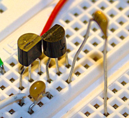
I grabbed a 2n3904 (NPN) and a 2n3906 (PNP) and a couple of DC blocking capacitors with the thought that I would breadboard a sample circuit and. Then I would hook-up my signal generator, oscope, spectrum analyzer, and micro-power meter.

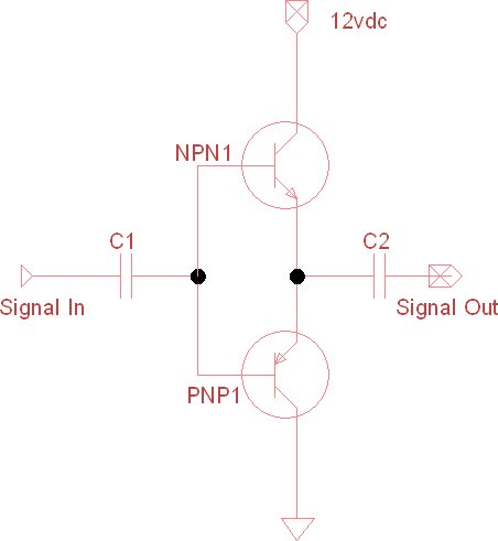
I decided to start simple (no diodes or bias resistors) to take some measurements. I did not remember what kind of power level that I was going to need to switch on the base of the transistors. It turns out that this particular configuration needs about -40dBm to start turning on the base.  (I tested it up to +10dBm which is as high as that particular signal generator went.)

  • I was seeing about +10dB of gain driven with -40dBm to +10dBm of signal source. The current draw was almost nil which is nice compared to a class A amplifier circuit.
  • Looking at the signal on my oscope it appears that it was running right the edge of Class AB as I was not seeing any distortion in the sign wave. (I would have guessed Class B from the design.)
  • When I looked the spectrum analyzer the harmonics where all very low... around -40dB from the fundamental frequency.
In summary while it did not create a ton of gain, +10dB is still pretty nice when it only took two 10 cent parts and 5 minutes of work. Two of these in parallel would probably make a nice final stage for a QRSS rig running 150-400mW range.

73 de NG0R


PS... on 1/28/12 I went back to mess with this circuit again and I am not seeing +10. <sigh> I am not sure what the deal is. I am guessing that I am not turning on base enough because I am seeing crossover distortion that was not there before.

By:
Category:
Comments Off

QSOs for Monday

I had to get up at 2am for a conference call on my day off so I decided to try to work a little overnight DX.

I was able to work PJ4C on 40m CW, 80m SSB, and 160m CW (Bonaire)


http://www.pj4c.com/


I have not worked a lot of 160m contacts in quite a while, but this was the hardest Q on that band that I can remember. The noise level was incredible and we really struggled to get the Q completed.  --But they are in log and it shows up online!

73 de NG0R