By:
Category:
Comments Off

Class AB amps from cheap parts

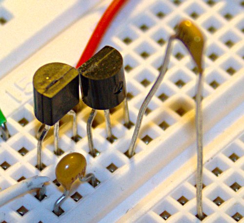
Yep, it is ugly...


This morning in between conference calls (yes, working on my day off again) I was I wondering about amplifiers. Specifically about using Class AB, B, or C amps.  It has been a while since I have played with push-pull amps so I pulled up some notes from the Internet to jog my memory.

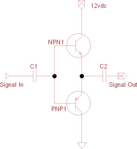
I grabbed a 2n3904 (NPN) and a 2n3906 (PNP) and a couple of DC blocking capacitors with the thought that I would breadboard a sample circuit and. Then I would hook-up my signal generator, oscope, spectrum analyzer, and micro-power meter.

I decided to start simple (no diodes or bias resistors) to take some measurements. I did not remember what kind of power level that I was going to need to switch on the base of the transistors. It turns out that this particular configuration needs about -40dBm to start turning on the base.  (I tested it up to +10dBm which is as high as that particular signal generator went.)

  • I was seeing about +10dB of gain driven with -40dBm to +10dBm of signal source. The current draw was almost nil which is nice compared to a class A amplifier circuit.
  • Looking at the signal on my oscope it appears that it was running right the edge of Class AB as I was not seeing any distortion in the sign wave. (I would have guessed Class B from the design.)
  • When I looked the spectrum analyzer the harmonics where all very low... around -40dB from the fundamental frequency.
In summary while it did not create a ton of gain, +10dB is still pretty nice when it only took two 10 cent parts and 5 minutes of work. Two of these in parallel would probably make a nice final stage for a QRSS rig running 150-400mW range.

73 de NG0R


PS... on 1/28/12 I went back to mess with this circuit again and I am not seeing +10. <sigh> I am not sure what the deal is. I am guessing that I am not turning on base enough because I am seeing crossover distortion that was not there before.

By:
Category:
Comments Off

QSOs for Monday

I had to get up at 2am for a conference call on my day off so I decided to try to work a little overnight DX.

I was able to work PJ4C on 40m CW, 80m SSB, and 160m CW (Bonaire)


http://www.pj4c.com/


I have not worked a lot of 160m contacts in quite a while, but this was the hardest Q on that band that I can remember. The noise level was incredible and we really struggled to get the Q completed.  --But they are in log and it shows up online!

73 de NG0R


By:
Category:
Comments Off

Arduino + DDS 60 = Sweep Generator


I am still bonding with the code from the Internet but I was able to make a small tweak and it is now sweep generator running from 1Mhz to 60Mhz. I need to increase the step rate or it will finish about the time I retire but the general principle worked.

I think that there are more efficient ways to handle writing out the data word groups to the AD9851 but I will need to better understand this before I can look at those kinds of things.  (crawl, walk, run, fall.)

73 de NG0R

By:
Category:
Comments Off

Arduino + DDS 60 = RF Fun


I have been meaning to find some time to work on interfacing an Arduino to a AD9851 or DDS60.

I got up early today for a conference call at work which got postponed to later in the day. (Yes, it is a weekend... don't ask.) Since I was up early and had breakfast out of the way I was thinking about some RF projects that I could start before the conference call later in the morning. (Yes, I am dialing into work on a weekend... like I said... don't ask.)

I decided to grab an Arduino Nano from the parts bin (next to some Uno's another Nano, some shields, some PICs, etc)  and a DDS60. I figured that there must be some existing code examples on the Internet to get me started.  My friend Google found some likely starting points.

http://blog.marxy.org/2008/05/controlling-ad9851-dds-with-arduino.html

I made a couple of quick changes to pin layout and removed the LED piece and saved it off as a sketch. The total time to connect everything up, build (steal) the sketch, and test was about 30 minutes.

Sure enough it is making RF. I was reading about 3.72dBm or about 2.25mW. With a signal at 10Mhz all of the harmonics thru 80Mhz were 54-62dB down from the fundamental. 90Mhz had a harmonic 47dB down and at 180Mhz it was 43dB down.  180MHz is 6x the crystal on the  DDS60 board.

For a quick project it was pretty fun and successful.  I need to bond with the code a bit so that I build my own code base that can talk to the AD9851 for some future projects.
---
The rest of my day so far has been mainly spent on conference calls for work (shhh... don't ask... it is a weekend.)

73 de NG0R