By:
Category:
Comments Off

Naked Breadboards


I did it!  ...I finally removed all of those projects... I finally stripped those breadboards bare.

I hate breadboards. But sometimes I still use them when I want to prototype something that I don't understand.  I am a noob at this electronics thing. There are times (a lot of them) where I need to stick a couple of parts on a board take some measures and see what happens and the breadboards are sometimes good for that.

I have been extremely busy at work for the last 18 months. So busy that work has greatly intruded into my free time. I had quite a few RF projects & experiments in flight some of which were on those breadboards. I noticed at least two QRSS transmitters with 10.140mhz crystals. I noticed at least one 7mhz QRP transmitter & pa based upon the crystal and NPN BJTs on the board.  --Who really knows what each of those things was supposed to represent as it was so long ago that it is beyond a blur.

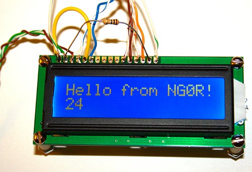
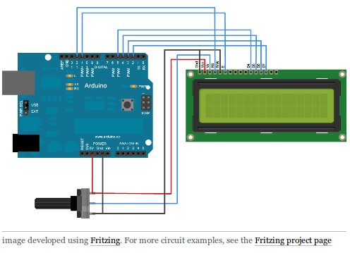
It finally hit me yesterday when I was trying to prototype something with my Arduino Uno and I had no open breadboards to work with.

This afternoon I removed all of the components. Now I have the chore of sorting those parts and returning as many of them as possible back into their proper parts bins.

I take the last couple weeks of cleaning & sorting (for a few minutes at a time) as an indication that I am about ready to start the winter RF building season. It is kind of like the geese migrating south for the winter flying in their classic V formations, my cleaning of the work bench and the acquisition of parts from Digikey, Mouser, Dan's Small Parts, and eBay is a sign that RF construction season is near by.

73 de NG0R

By:
Category:
Comments Off

Arduino - Hello World


I figured that I needed to do the standard "Hello World" tests with the LCD since this was a new platform for me. To be real honest it took me longer to wire up the leads to spare LCD than anything else and even that did not take more than about 15 minutes.

Parts:
A short section of cat 5 (so that jumper wires are easier to track with some color variation)
10k ohm pot
10 ohm resistor
16x2 LCD
Arduino Uno

The online notes that I referenced for this tutorial omitted the circuit details for wiring up the LCD backlight (aka: the LED on pins 15 & 16) but a couple of quick searches resolved that little detail.


I also wanted to take the experiment and draw it out in Fritzing to see how well it would help visualize the example for the web. It was pretty easy for using it for the first time. The picture above took about 10 minutes to draw out.

For the code I used the Hello World example sketch. Once that was working (first try) I made a quick tweak to it and sent it back to the board for pictures.

---------------------

/*
  LiquidCrystal Library - Hello World, NG0R
 
 Demonstrates the use a 16x2 LCD display.  The LiquidCrystal
 library works with all LCD displays that are compatible with the
 Hitachi HD44780 driver. There are many of them out there, and you
 can usually tell them by the 16-pin interface.
 
  The circuit:
 * LCD RS pin to digital pin 12
 * LCD Enable pin to digital pin 11
 * LCD D4 pin to digital pin 5
 * LCD D5 pin to digital pin 4
 * LCD D6 pin to digital pin 3
 * LCD D7 pin to digital pin 2
 * LCD R/W pin to ground
 * 10K resistor:
 * ends to +5V and ground
 * wiper to LCD VO pin (pin 3)
 
 This example code is in the public domain.

 http://www.arduino.cc/en/Tutorial/LiquidCrystal
 */

// include the library code:
#include

// initialize the library with the numbers of the interface pins
LiquidCrystal lcd(12, 11, 5, 4, 3, 2);

void setup() {
  // set up the LCD's number of columns and rows:
  lcd.begin(16, 2);
  // Print a message to the LCD.
  lcd.print("Hello from NG0R!");
}

void loop() {
  // set the cursor to column 0, line 1
  // (note: line 1 is the second row, since counting begins with 0):
  lcd.setCursor(0, 1);
  // print the number of seconds since reset:
  lcd.print(millis()/1000);
}


---------------------

Overall it was a pretty easy experience.  It worked as expected (a novel idea) which helps to grow your confidence level. I am pretty impressed with the tutorials and examples. The Arduino team has done a good job creating a tool that has a low barrier to entry.

73 de NG0R

By:
Category:
Comments Off

Schematics and images for documentation

When I am working on a electrical or RF design project I like to create nice documentation for the effort. Frequently I am sharing my ideas with friends over the Internet as I work through the iterative design process. Creating those images usually has been either JPG exports or screen-captures from my schematic capture or PCB design software. (Things like TinyCad, Free PCB, PCB Express, Eagle, KiCad, etc)


Today I was reading a tutorial at: http://arduino.cc/en/Tutorial/LiquidCrystal
and I noticed the nice visual (physical) representation of the circuit.  I noticed that it was created with a tool called Fritzing. http://fritzing.org/


It turns out that Fritzing is an Open Source project. It allows you to draw images like the one above, it does the schematic capture, and PCB layout with auto-routing.  It appears that you can export the files as images to web, gerber, and also send them to fab houses. --The tool will run on Windows, Mac, and Linux.

I installed it on my Ubuntu 11.10 64bit machine and had it running in about 2 minutes. I am going to work on an Arduino tutorial today (I am still getting my feet wet with the platform) and as part of that effort I will try to draw out the project with Fritzing to see what it can do. I see a lot of potential for this tool if it performs well.

73 de NG0R