By:
Category:
Comments Off

More... Reverse Biased Diodes

I am still looking for some other options for a better method of handling my tuning for my next QRSS prototype. I decided to revisit the bread board and take some additional measurements.


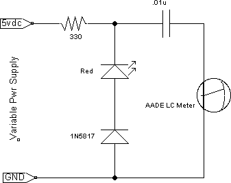
I was wondering if a series red LED + 1N5817 (both are reversed biased) might give me the range that I need within a 0 to 5vdc window. (I will be using a PIC 16F628A for pulse width modulation so 5vdc is my upper range.)


The results are promising based upon the graph below. My design goal is about 12-20pF. I think that I need about 18pF based upon some earlier prototypes.


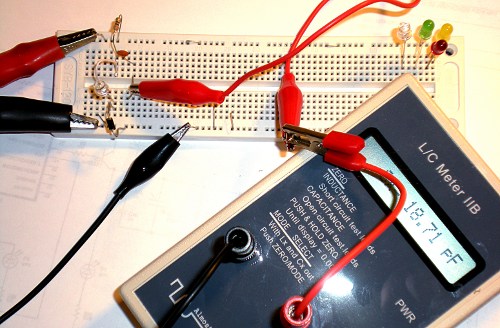
This picture shows you what a pain it is try to measure these parts and then swap out new combinations. At some point I will design a little prototyping adapter for my LC meter  so that I can do this right on the front of the meter without any jumpers.


I tried one other combination that provided a very granular range.
Reverse biased in series 1N5817 + Red Led + 1N5817
0-5vdc = 6-18pF


I have four different variations that I have tested over the past couple of days that will get me into the ball park to differing degrees. (granular tuning vs. tuning range vs. parts count)
  1. Reverse Biased 1N5817... a bit too much capacitance by it's self
  2. Parallel 10-30pF variable cap + rev biased Red LED
  3. Series rev biased 1N5817 + rev biased Red LED
  4. Series rev biased 1N5817 + rev biased Red LED + rev bias 1N5817
Option 2 provides the best flexibility
Options 3 & 4 provides more granular tuning

I will need to ponder this a bit to determine which path I like the best.

73 de NG0R


By:
Category:
Comments Off

Skywarn on a Friday

K0MPX asked us to activate the Meeker Co. Skywarn group twice this afternoon.

Here are some images of the second trip near Pigeon Lake south of Dassel, MN

Overshooting tops + rainbow


Crackberry photo of the radios in the truck


Crackberry photo of me in the mirror sitting in the rain


Crackberry photo thru the rain of the rainbow


Overshooting tops near Dassel, Mn


Trip1: Kingston, Kimball, Watkins, Eden Valley and back
Trip2: Kingston, Dassel, Pigeon Lake


73 de NG0R

By:
Category:
Comments Off

Reverse Biased LED for QRSS

I managed to sneak to the workbench after everyone went to bed  :-)

I wanted to see if I could find a good diode or LED + capacitor combination that might work for my QRSS project. So I placed some likely parts on the breadboard and attached my AADE LC meter.


Since I plan to use a PIC 16F628A to pulse width modulate the LED I figured that I should keep the DC voltage on the breadboard between 0-->5vdc since the PIC will use a 5 volt regulated source. It turns out that I have about 200 red LEDs from an eBay purchase that work nicely in parallel with a 10-30pF variable capacitor.


With some real quick testing it looks like I can dial this in between about 8-50pF pretty easily. I think that I need about 18pF for the current QRSS design that I am working with. This looks like it should allow me to vary the frequency of the transmitter fairly easily.

The QRSS sub band is 100Hz wide. If you are doing any sort of FSK activity the general rule is to only run about 5Hz of shift since the sub band is so small. The last time that I tested this concept I think that 5Hz of shift at 10MHz is about .5pF.  That is a tough value to try to achieve without something like varactor diode. A reverse biased LED can fill this role pretty nicely.

The variable capacitor on the left should allow this to be rescaled for other bands fairly easily.

The LED will allow for the 5Hz frequency shift.

At some point in the near future I need to write a little test harness for the PIC and put on a breadboard. That would allow me to measure this as a complete circuit with the PWM running.

73 de NG0R


By:
Category:
Comments Off

Reverse Biased Diodes

Tonight I was playing with the idea of using reversed biased LEDs and Diodes as varactor diodes or variable capacitors. Hans Summers has done a lot of testing around this concept for use in CW and QRSS transmitters.

Here is an example of what a particular diode exhibited during a test:


I mocked up a simple test on a bread board and used my AADE LC meter to take some basic measurements. This is largely based upon a picture that I saw on Han's site.


I used a variable bench power supply to run the tests. I might build a simple printed circuit board fixture for future tests so that I have solid tool with reproducible results.

Here is the raw the data for this test:


Overall it was a fun experiment that shows some practical promise for some future projects.

73 de NG0R

By:
Category:
Comments Off

QRSS Prototype

I finally got around to applying power to the prototype this afternoon.

I did not spend a lot of time but here is what I recorded in about 20 minutes of bench time:

I did not test it with a PIC, but I instead used the header pins.

Specs:
  • 12vdc  @.34amp
  • 26dBm or about 400mW of RF @ 10,140,030MHz
  • All harmonics are at least 47db down

Good: 
  • It made a LOT of RF
  • It was extremely clean
  • It starts up reliably

Bad or unclear:
  • It does not appear that my frequency shift with the second variable capacitor is working
Original Design Notes: /blog/2010/07/25/latest-qrss-pcb/

I will need to spend some more time with it when time permits... need to run off to dinner with my family.

73 de NG0R

By:
Category:
Comments Off

Camera Intervalometer

Here is a project that I have pend thinking about building using a PIC.  This designer used an AVR but almost any processor could handle this task.

http://kalshagar.wikispaces.com/ardTimeLapse


The pin out for the plug is pretty simple.  When time permits I will have to throw some parts on a bread board. I will likely used some fixed time values that are selectable vs. using pots.


By:
Category:
Comments Off

QRSS Prototype


Here is the prototype with the parts installed. Some time this week I would like to apply power to it. I can test it with the two header pins in place of the 16F628A. That should let me tune up the oscillator and the fsk shift with the two variable capacitors. 

I have some existing QRSS code that should be pretty easy to port. I think that I will just need to update the pins that I decided to use. (My existing code is setup to echo the message and status on the LCD display. For simplicity with the initial prototype I decided to leave out the LCD.)

I have a couple of  additional features that I am pondering adding to the design. Parts count/price + available memory will be a couple key considerations.

73 de NG0R

By:
Category:
Comments Off

Latest QRSS PCB

Here is another QRSS prototype that I am working on. This one will support standard single frequency and dual frequency CW. (I will add FSK in a future version of the board.) The design will use a PIC 16F628A for the keying.  It is likely that I will need an additional amplifier stage but I want to assemble and measure this prior to adding too many more features. (It is easier to debug & test this if I control how much change I introduce in each version of the prototype.)

Click on the image to see a larger version of the schematic.


I then exported the TinyCad schematic into FreePCB to layout the board (below). 


I then exported the board layout into the appropriate Gerber and PNG formats.


I then printed the artwork on some blue print and peel paper with my laser printer and then taped it to the 3x4 inch piece of single sided circuit board.


I then ran the combo through my modified laminator to transfer the laser toner to the circuit board. Four passes through the laminator is enough to bond the toner.


I then drop the combo into a container of water. After about 60 seconds the blue print and peel is ready to remove from the board. Once the board is dry I then applied some green foil to the PCB to seal the toner. (This is the first time that I have tried the the green foil.  It was a mixed success... it actually reduced the quality of the PCB because the traces were not as clean as the raw toner was.  --Live and learn.)


Since it is summer time I decided to etch the board in the garage to reduce the fumes. I have a make-shift table setup on two saw horses. I poured about 1/2 a quart of homebrew etchant into a one gallon plastic container. (The container is a $2 piece of tupperware from Walmart.... great for etching boards.)


I placed the board into the etchant for about 10-15 minutes. I agitated the container about every 3-4 minutes with a quick swirl motion. 


After the copper was dissolved I used some rubber gloves to pick up the board and transfer it to a container of water to rinse it off.  The copper is green in this picture because the green foil sealer is still on the board.


I then rinsed the board with some Acetone which dissolved the foil and laser toner.


I then drilled the holes with a Dremel press and some #67 drill bits.  I used some slightly larger bits for the ZIF and BNC connectors.


I will try to get the parts stuffed and soldered down Monday night. After that I should be able to measure the power and validate that the harmonics are down at least 43db.

This is not the best board that I have etched so I would only rate it about a 7 out of 10 because of the green foil.

It is the most complex that I have tried etch because it was originally designed a dual sided PCB. The ZIF and BNC provided a couple of initial challenges but I think that I have solved those as well.

This has been a very enjoyable project... lots of learning and challenges.

73 de NG0R

By:
Category:
Comments Off

Wall Cloud


Here is a picture of a wall cloud in Kingston, MN taken on 7/17/2010

The group of amateur radio operators in Meeker Co activated Skywarn for the weather service three times on Saturday between 1pm and 11pm.  That made for a long day watching the skies