By:
Category:
Comments Off

LTSpice


I am trying to figure out how to use LTSpice. Craig AA0ZZ provided an oscillator model
to use as an example.


Here is an interesting PDF that I found that provides some initial hints on using
the tool:

http://pages.suddenlink.net/wa5bdu/ltguide.pdf


Drawing the schematics are pretty easy for anyone that has used a CAD program or something
like Visio. Being able to see RF is quite a bit more challenging.


I have LTSpice running under Wine on an Ubuntu 8.10 VM guest.


By:
Category:
Comments Off

Some more Q's in the log


I am at home with my kids for spring break. I have managed to have the radio in the
shack turned on quite a bit. I have been trying to make a point of putting a few q's
into the log on a more regular basis. Here a couple of them that I have worked in
the past 24 hours or so.


My two older sons thought that it was kind of neat to work people in Russia and Japan.
It does not mean much to them yet other than an interesting voice or some dits and
dahs from 1/2 way around the world.


The Europeans were getting ready for a contest this weekend. Lots of interesting callsigns
emitting RF


By:
Category:
Comments Off

2009 Field Day Antenna Ideas


I am starting to think about my options for antennas for Field Day 2009. I will be
camping @ Monson Lake State Park, MN. I will be operating QRP in class 1B1B. (K2 +
battery @ 5w) I would like to have 2 antennas that will cover 20/40/80 and fit
within a modest size campsite.


There are lots of simple options for 20/40 with wire dipoles. 80m becomes a challenge
because of the size of the antenna @ a 1/4 wave length. I will need to try to check
out the campsite ahead of time to see if a 1/4 wave dipole is an option. Assuming
that I need to go with a plan option for 80m I have an idea for that as well.


20m/40m Dipole Idea


KD1JV inspired 20/40 antenna with some tweaks.


---Trap-----Center-----Trap----

Center to Trap = 16.363'

Trap to End = 13'

Trap is a T50-2 with 24 turns or 2.8uH + a 47pF cap across the core.

A T50-6 with 26 turns or a FT50-61 with 6 turns would also work.


Tuned for 7.05 mhz and 14.05 mhz @ 50 ohm


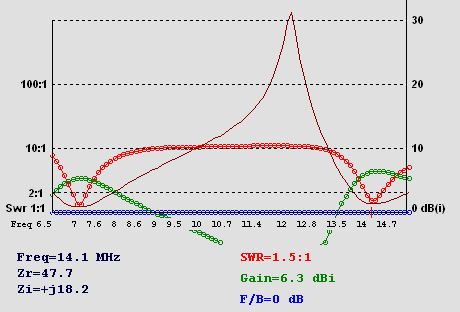
The 20/40 antenna is modeled @ 30' of elevation. The SWR will drop a bit more as the
elevation increases. 30'-40' is a pretty good comprise height for this antenna.
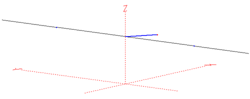


--------------------


80m Antenna Idea


80m inverted L with an elevated radial @ 75 ohm


The base is elevated 6' above the ground.

The elevated radial is 10' long.

The vertical section of the antenna is 30' tall (top of the vertical section is @
36')

The top hat wire is 37.5 feet long.


The natural feed point is SWR 1713:1 or Zr/Zi = 20.3, -j1613


Given the ugly feed point values there are some easy options to get a match.
I have chosen two different L networks options because of their ease of construction
and semi-achievable parts. (Almost anything is possible in a model... but
in the real world Mr. Murphy general has some harsh reality checks for us.)


Option 1 for 75 ohm coax


C-L Lo Pass L-Net

Shunt: 782.43 pF, Series: 73.96 uH, Q=225

73.96 uH = 13 turns on a FT50-43


Option 2 for 75 ohm coax


C-L Hi Pass L-Net


Series: 18.2 pF, Shunt: 43.73 uH, Q=225

43.73uH = 10 turns on a FT50-43


There is a lot of room for improvement in the 80m model. For 30 minutes of modeling
it seemed like a decent start.


I happen to have some toroid cores, some variable capacitors, and some door knob capacitors
so these are all values with in reach of my work bench collection of parts. In case
you are wondering why some of the models have a 75 ohm feed point... 75 ohm coax is
cheap. We are talking about pennies per foot for RG6 which I happen to have a few
hundred of feet on a spool near by.


OK... in reality the 80m inverted L will suck. It
is too narrow and tweaky. It was a fun exercise... but I need something more realistic.
(An 80m dipole takes a LOT of space. Space & efficiency is what I am
competing against.  I need to visit my campsite ahead of time to see how much
space I have to work with.)


By:
Category:
Comments Off

QSOs


Kind of a wild idea... turn on the radios, connect the coax, and make a couple of
contacts.


T77C    14.022mhz   CW

5N0OCH  14.016mhz   CW

P40YL   14.081mhz   RTTY


These were made on my Icom 756 @ 100. (The K2 is listening to 30m at the moment.)


OK... back to the bench in the over room. I am working on building a direct conversion
80m CW rig.


By:
Category:
Comments Off

Electronics Info


I found some interesting Javascript for doing conversion calculations.

It has a nice Inductor and Capacitor feature for when you can't remember which way
to move the decimal point.  :-)


/content/conversion_calc.htm


I was looking from some info on Toroids and the number of windings.


/content/toroid_turns.htm


I liked the toroid info that I made a screen capture of the info from the website.
The credit to the original author is listed above the image. I have gotten burned
in the past were someone has great info and then their site goes dark. Making a screen
capture like this solves that problem.


By: Comments Off

K2 - Transverter module - Night 1


I assembled the module before dinner and then applied the changes to the RF board
after dinner. The unit powers up with no warnings so I think that it is going to work.
I will need to go thru the 40/60 alignment steps and then test the transverter power
out piece as well.


Frankly I am tired enough tonight that I don't feel like pulling out the stuff that
I need to do the final tune-up and testing tonight. (160m/Top band is sounding awesome
as I type this up.) I think that I am going to call it a night.


I will probably do the alignment and tune-up after I install the AF Out mod. Maybe
I can tackle this on Saturday or Sunday this weekend. That would officially finish
my K2 project. At which point I can try to operate the K2 on a semi-daily
basis and move onto the next project. (I have lots of projects that have been on hold
while I finish the K2 project.)


The 60m/transverter module probably took about 2.5 hours of bench time to
complete. 


By: Comments Off

K2 - 160m module - Night 2


I have partially resolved my problem.


It appears that my problem is within the 80m/160m bandpass filter.


For some reason L4 is extremely sensitive now. I can detune it with my hand or a plastic
screwdriver. After about 45 minutes of poking around with an RF probe I was able to
figure out that the problem is within the bandpass filter and eventually get
the circuit tuned up.


I am still not sure that 80m and 160m are 100% stable yet. I am getting 13-15w out which
is pretty good. I suspect that there is still a ghost in the circuit that I need to
chase down. Time will tell.


Top band sounds great on the K2.


I will probably move onto the transverter module and then home brew an "AF out" circuit.
I am really looking forward to being able to operate the radio and move on to a new
project/kit.


By: Comments Off

K2 - 160m module - Day 1


Since the other module went so smoothly I decided to start the 160m module as well.


This module started very nicely and was pretty quick construction. The toroids are
not a big deal any more since I have a solder pot to clean up the leads prior to attaching
them to the circuit traces.


Things were going all together too well... and then Murphy struck.


I am getting a "LO P" message on 80m and 160m. The relays work and I can hear signals
on 80m and 160m... but no RF. I am not exactly sure why at this point. I sent an email
to the reflector to see if one of the other K2 builders  has been thru this before.


I had about 60-70 minutes into this module when I got stuck and had to shift to troubleshooting
mode.