By:
Category:
Comments Off

6m opening

Tonight after the severe weather cleared I reconnected the coax and rotators cables and had a pleasant discovery.  6m was open looking to the SE. In about 25 minutes I managed to work 43 stations while running. I have decided that my grid is "rare enough" that I can run vs. operating search & pounce.


Initially I was working folks in 2, 3, and 4 land and then the propagation shifted and I worked some 8's and then someone in Idaho off the back of the beam.

Spring E's on 6m is a fun time to play with the radios.

73 de NG0R

By:
Category:
Comments Off

Updated Ports for Shack

I recently rebuilt the shack PC. In the process I moved to a new version of Ubuntu. I am now running 10.4 32bit on this machine. During the rebuild I noticed that some of my Serial and USB port numbers changed.

Linux Native
/dev/ttyS0 = PSK Warbler
/dev/ttyS1 = former port for Rigblaster Pro
/dev/ttyS2 = former port for IC-756 CIV
/dev/ttyS3 = Elecraft K2
/dev/ttyUSB0 = Rigblaster Pro (IC-756)
/dev/ttyUSB1 = IC-756
/dev/ttyUSB2 = K1EL Keyer

I like to keep the notes on my blog for ease in referencing them in the future.  :-)

73 de NG0R

By:
Category:
Comments Off

QRSS programming

I finally got back around to writing some code tonight.


I had been trying to determine how I wanted to parse out the text from the call sign message. The call sign messages might be different lengths so I was working through some different logic options.

Right now my development tool is showing that I have about 730 lines of code... probably 75 lines are really line spaces that don't really count.


Currently I can handle sending CW for 51 different characters in the message.   That is what really increased the amount of code in this project. (It is simple code... but still has a cost tied to it.)

Right now demo board and code is just echoing out the beacon message on the LCD display and flipping some pins that are not tied to anything right now. I probably need to think about moving the PIC 16F628 to a breadboard or printed circuit board soon to start testing the integration with rest of the project or at least a mock up of the project.

I need to write a little bit more code once I decide on a few more user interaction details. (Aka: letting the user choose between CW and DFCW as an example)

I had hoped to integrate a frequency counter in this project that might push me to a chip with more memory than the 16F628. I will need to look back through my code looking for places to reduce size.

Overall this is a pretty cool project. It is giving me a chance to do some RF design and embedded development design work. It is kind of fun to sling some code in the compiler once in a while.

73 de NG0R

By:
Category:
Comments Off

6m is open again tonight

Another evening with lots of activity on 50mhz.

I think that I put another 18 Q's into the log tonight.

I am going to try to pull the plug and work on some PIC programming for a while tonight. It is hard to stay away from the radio when I hear a good opening.

I enjoy a good 6m opening much more than playing HF any day.

73 de NG0R

By:
Category:
Comments Off

6m opening for NG0R

I woke up from an after dinner nap to discover another nice 6m opening.


I had a nice pipeline between Minnesota to Utah & Arizona.


The image above shows what my dual screen Linux shack desktop looks like.  I am running on 6m with my Icom756 while my Elecraft K2 was receiving WSPR on 30m.

73 de NG0R


By:
Category:
Comments Off

N2BEN running on 6m

Early Sunday evening 6m was open.

Ben decided that he was going to run on 6m during the band opening. So I switched the antenna from my shack over to the room where the boys have the FT-450AT setup. With a little bit of assistance Ben (N2BEN) ran 12 stations in about 15-20 minutes.

I noticed that on one of the spotting maps that someone had spotted Ben running on 50.140 SSB.

Ben made good use the of built in Voice Keyer to make sure that people could find him up from the calling frequency. Ben is now a big fan of the magic band.

73 de NG0R

By:
Category:
Comments Off

Whispering

I took a quick break over my lunch break to grab a screen capture from my shack.


While I am working am letting the shack PC (Ubuntu 10.4) try to capture WSPR traffic from my Elecraft K2.  Since I am working they are sitting idle and might as well "play radio" without me.  :-)

73 de NG0R (I am done with my 10 minutes for lunch and it is time to go back to work.)

By:
Category:
Comments Off

EFHWA project

Several people I know have End Fed Half Wavelength Antennas.  --I did not, until this weekend.

Most of these boxes are pretty simple systems that are designed for QRP type power levels. QRP is fine for me, but my 9 & 11 year old sons (N2BEN and N0AEA) might get a little frustrated trying to make QSOs at 5w. I decided to make a 100w capable version for use with their radio.

The picture below shows the final result of my version 1.0 EFHWA tuner box. Let me explain how we got there so that it makes more sense.

The knobs for the capacitors & switches + the switch level all are externally accessible on my project box. They are cropped out of this picture... but they are really there.

When you look at the schematic below there are three main items:
  1. Transformer used for impedance matching
  2. LC resonate circuit (Secondary of the transformer + the variable capacitor)
  3. High impedance load to simulate an antenna (4.7k resistor shown with the dashed lines since it is optional)
Let's focus on making the LC circuit resonate at the frequency of interest.


Most people are using a T50-2 or T50-6 toroid with about 3:24 or 3:27 turns.

24 turns on a T50-2 transformer is about 2.92uH of inductance. (This is an important detail to know otherwise the math in the later steps will not work.)


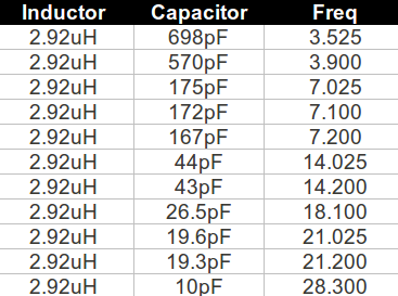
If we take 2.92uH and a known frequency we can figure out what size capacitor that we need to resonate this circuit.


I used the N0FP LC spreadsheet (above) to figure out what size fixed capacitor I might need across several bands. This gave me an idea of what size variable capacitor that I might need to cover several bands.  The list below shows that a 25-175pF variable capacitor + our 2.92uH inductor might cover 40m --> 18m.


The reality is that for medium power parts it is hard to find a variable capacitor will cover a range as wide as what I was looking for.
  • The ones that I had in my junk box stash are close but not quite close enough.
  • I then looked at my collection of door knob capacitors to see I could find a combination of variable+doorknob that might work... nada.
  • I then decided to look at using two variable capacitors in series. This helped with 17m and 20m but then made it hard to get a match on 40m.  I ended up using a switch so that I could swing the second capacitor in/out of the circuit.
You should also notice that I scaled this from a T50-2 to a T130-2 toriod. (To make sure that it could handle 100w.)  16 turns on a T130-2 core is ~2.92uH.

Instead of a fixed turns ratio on the transformer I put a series of taps on the primary so that I use a 5 position switch to select the number turns on the primary winding.
1:16, 2:16, 3:16, 4:16, 5:16

To test this I applied a 4.7k resistor to simulate the antenna and counterpoise. Sure enough it will tune up on 40m, 30m, and 20m.  17m is still looking a bit elusive hinting that my minimum capacitance is not quite small enough. I will need to test it in the real world with an antenna and see how it plays.


As you can tell from my first photo and this schematic... this little project became a bit more complex than I originally planned. (Because of the power levels and number of bands that I wanted to be able to cover.)

How to tackle this project:
  1. Make a LC resonate on a specific frequency. (You can use a different core type and size, you will need to calculate amount of inductance to use in your LC formula)
  2. Then we use the primary to secondary ratio on the transformer to transform our 50 ohm radio and transmission line to our high impedance antenna. (Simulated by the 4.7k resistor at our workbench shown with the dashed lines in the schematic.)
Obviously there is a TON of detail that I am not getting into in a single post. The links below provide some good background on the EFHWA antenna. These are the primary articles that I used to get up to speed for my project:

http://www.swlink.net/~w5jh/efhwa_at.htm

http://www.aa5tb.com/coupler2.html

http://www.aa5tb.com/efha.html


http://www.aa5tb.com/efha_wrk.html

Next steps:
  • I need to measure and cut some wire a 1/2 wavelength long on the frequencies of interest.
  • Test them on one of our upcoming camping trips.
I will probably build a QRP version of this box. Finding a capacitor for the range that I need should be easier at low power.

73 de NG0R


By:
Category:
Comments Off

OSCAR (Satellites)

One of sons (Ben, N2BEN) wants to make a satellite QSO. So the other day I was looking at the software available for my PC running Ubuntu (version 10.4) that is the primary computer for interfacing to our radio adventures. I found a neat program call GPREDICT.


After a couple of minutes of configuration I have it tracking the most of the satellites that AMSAT lists as operation or semi-operational.  It is has a very nice looking display. In fact it is so nice that I leave it running all time on one of the two screens on that PC.

List of Satellites:
http://www.amsat.org/amsat-new/satellites/status.php

List of frequencies:
http://www.amsat.org/amsat-new/satellites/frequencies.php

Maybe this summer we can find an afternoon to make some qso's via satellite for Ben's log. (maybe Jacob N0AEA will want to play too.)